The challenging demands of over time trucking, which involves covering long distances both day and night, contribute to widespread sleep deprivation among truck drivers. Among car drivers as well due to late night driving resulting fatigue and drowsiness play a significant role in causing major accidents on the roads. According to a study conducted, fatigued drivers who dozed off at the wheel were responsible for 42% of traffic accidents on the 300 Km Agra-Lucknow Motorway in 2022, with Uttar Pradesh experiencing a high number of fatalities. With this project we aim to create a highly accurate and highly efficient sleep detection system for drivers that dose off during the night and even during the daytime. Using this system, we aim to alert the driver in case he/she doses off using a buzzer or other alarming mechanism preventing the accidents which in turn will save a lot of lives and promote safe travels.
Theory and Brief Overview
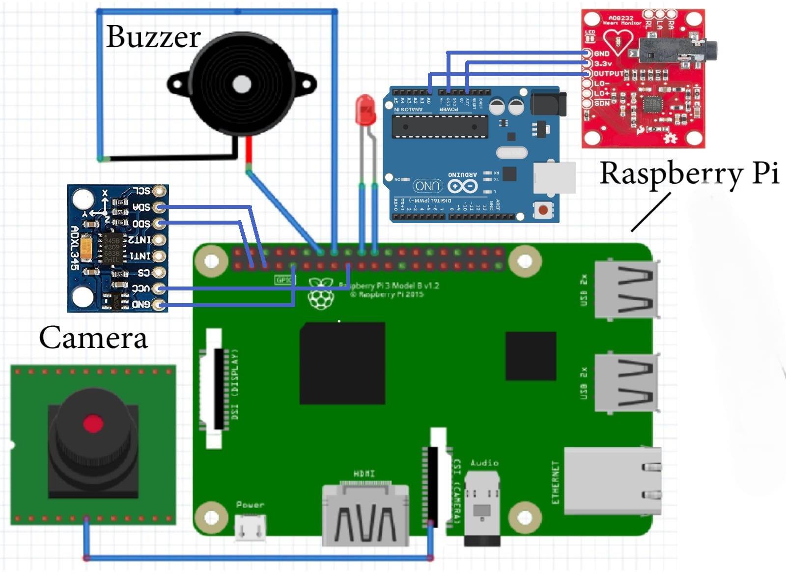
We are using Raspberry pi 4 and Arduino Uno microcontroller combined together to create a system that can detect sleepiness of the driver. The idea is to combine camera module, ADXL345 and AD8232 in aiding each other resulting in a system to detect if the driver is sleepy or not. An alarm system is also embedded which will alert the driver and prevent accidents from happening. We are using Camera module to detect drivers' facial expression such as yawn detection and closing of the eyes, ADXL345 for detecting unusual behavior of the steering wheel and AD8232 for reading EEG value for detecting the waves when the person is asleep or not.
Components Used
- Raspberry Pi 4B-Key features of the Raspberry Pi 4 include a quad-core ARM Cortex-A72 processor, which provides a substantial boost in processing power. Its GPIO (General Purpose Input/Output) pins enable hardware interfacing and its DCMI interface enables various image processing capabilities.
- Arduino UNO- The board is based on the Atmega328P microcontroller, which provides a balance of processing power and flexibility for various applications. We are using the board mainly for its ADC component that will be used to take the values from AD8232.
- 5MP Camera Module-The Raspberry Pi Camera Module is a low-cost IMX477 camera interface for the Raspberry Pi. It features a 5-megapixel sensor that captures high-quality images and videos, and it supports uncompressed RAW and JPEG capture modes.
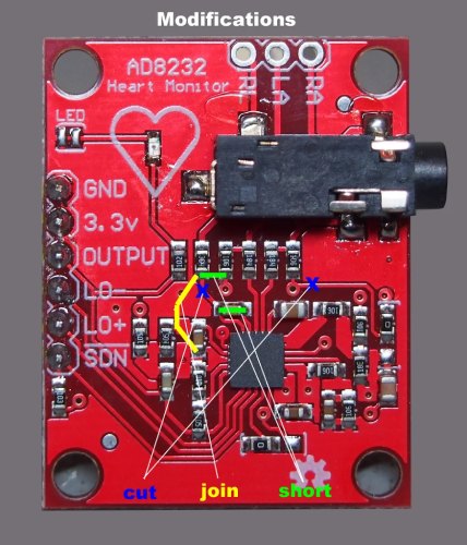
- AD8232-The AD8232 is a specialized integrated circuit (IC) designed for monitoring and processing bioelectrical signals, specifically in applications related to electrocardiography (ECG).It amplifies and filters the small electrical signals generated by the heart, making them suitable for further processing and analysis. In our case we will be modifying it to detect EEG signals.
- ADXL345-he ADXL345 is capable of measuring acceleration along three orthogonal axes (X, Y, and Z). This makes it suitable for applications were understanding movement and changes in velocity in three dimensions. The sensor provides digital output through I2C (Inter-Integrated Circuit) and SPI (Serial Peripheral Interface) communication protocols.
- Buzzer-A DC buzzer is an electro-mechanical device that produces sound through the vibration of a diaphragm or a piezoelectric element when an electric current is applied. DC buzzers are powered by direct current, typically in the voltage range of 3V to 24V.
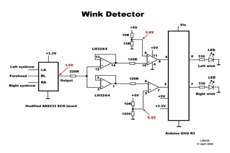
- LM324N ic - This is a quad op amp ic which is being used as comparator for turning the output coming to 5V or 0v depending on the need.
- Resistors-1- 220K ohm resistor, 2-120K ohm resistors, 1-15K ohm resistor, 2- 10K ohm resistors, 1–1200-ohm resistor.
Circuit Diagram
Modifications made in AD8232.
Connection of AD8232 with LM324N ic and Arduino uno
Results
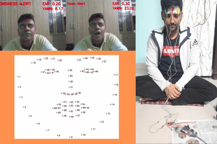
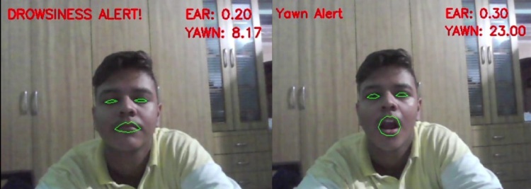
Picture showcasing sleepy eye and yawn being detected and the alert being shown with red color.
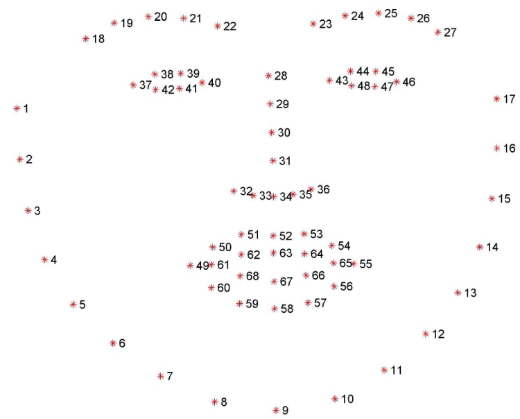
The DLIB 68 points mask mapping the face into the points.
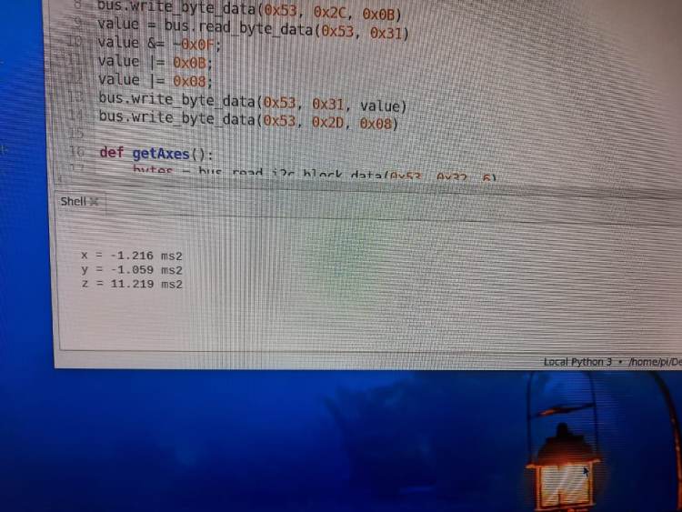
Values of the ADXL345 sensor being taken using Raspberry pi for further analysis
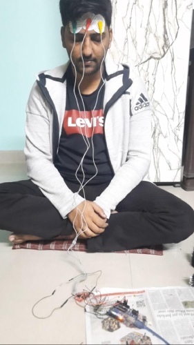
Glowing of the on board led on closing of eye for a long time (won’t work for normal blink of the eye)
Software and Hardware Integration (Working)
CAM Module, Raspberry pi and Buzzer
- Initially we are taking the values from the Raspberry pi CAM and feeding it into Raspberry pi 4 thonny ide. Here the processing of the live video feed is done where first the face of the user is detected by haarcascade_frontalface_default.xml. After the face detection is done using shape_predictor_68_face_landmarks.dat the face is divided into 68 landmarks.
- After successfully dividing the face into 68 points the EAR and YAWN threshold is calculated. The EAR is eye aspect ratio which detects if the eye is closed. We have also put a timer of 3 sec to differentiate between blinking and sleeping.
- The Yawn threshold is nothing but the distance between upper and lower lip which is used to detect yawn the yawn threshold is adjusted such that it differentiates between yawning and talking.
- In case any of the YAWN ALERT or DROWSINESS ALERT is raised the alarm or in our case the buzzer pin goes HIGH in order to alert the asleep driver
ADXL345 and Raspberry pi
- With ADXL345 we are trying to map the normal behavior of the steering wheel when the driver is awake i.e. the acceleration of the steering wheel will be normal levels
- Whereas in case of an asleep driver he/she may be changing lanes suddenly hence the acceleration of the wheel of will be more. This is based on the techniques used in cars such as XUV500.
- We have initially connected the adxl345 with the Raspberry pi using I2C which means the connection has been made using SCL and SDA pins. While the sensor is powered using 3.3 V.
- SMBUS is used to connected and communicate the Raspberry pi with the I2C devices, which includes the read and write commands.
- Initially I2C device was detected i2cdetect -y 1 and the slave address 0x53D was given as the output on the terminal. First the device is put in measurement mode. After that the ADXL345 was put into read mode. After which the data of acceleration of X, Y, Z axes was taken and if the X axes was more than ms2 a warning signal is printed showcasing irregular behavior.
Arduino and AD8232
- AD8232 is a device that acquire, amplify and compare the weak electrical signals generated by the brain during. It is particularly sensitive to the low-amplitude signals associated with EEG measurements. It is the on the basis of the waveform patterns generated the by EEG signal that helps understand the sleep condition. It is using these waves we are trying to figure out the condition in case of an asleep person and the condition in case of awake person.
- The AD8232 patches are first connected above the RIGHT Eye, Center of the forehead, LEFT Eye, then the connections are done to Arduino with the SDN, LO +, LO-, OUTPUT, 3.3V and GROUND.
EEG Signal Processing:
Adjust the circuit to process EEG signals instead of ECG. The AD8232 output, originally hovering around 1.5 volts DC, will now reflect EEG activity.
Extended Wink Detection:
- Modify the comparator thresholds to detect prolonged winking indicative of sleep-related behavior.
- Left-eye winking raises the output waveform towards 3.3 volts. Adjust the threshold accordingly.
- Right-eye winking lowers the output waveform towards zero volts. Adjust this threshold as well.
Future Scope and Updates
- We are aiming to use the raspberry pi zero version to reduce the cost of the system.
- Increase the accuracy of the signal obtained and processed by the AD8232.
Team Members:
- Pratyush Kaushik
- Ayaz Mahboob
//Code AD8232 with Arduino
#define OPEN LOW
#define CLOSED HIGH
#define ON HIGH
#define OFF LOW
const byte LeftEye = 4;
const byte RightEye = 5;
const byte LeftLed = 13;
const byte RightLed = 6;
bool LeftEyeState;
bool RightEyeState;
unsigned long LeftStopTime;
unsigned long RightStopTime;
unsigned long StopTime = 2000000UL;
void setup() {
Serial.begin(115200);
pinMode(LeftEye, INPUT_PULLUP);
pinMode(RightEye, INPUT_PULLUP);
pinMode(LeftLed, OUTPUT);
pinMode(RightLed, OUTPUT);
LeftEyeState = CLOSED;
RightEyeState = CLOSED;
digitalWrite(LeftLed, OFF);
digitalWrite(RightLed, OFF);
LeftStopTime = micros();
RightStopTime = micros();
}
void loop()
{
if (micros() > RightStopTime) {
LeftEyeState = digitalRead(LeftEye);
while (LeftEyeState == CLOSED) {
digitalWrite(LeftLed, ON);
LeftEyeState = digitalRead(LeftEye);
LeftStopTime = micros() + StopTime;
}
digitalWrite(LeftLed, OFF);
}
if (micros() > LeftStopTime) {
RightEyeState = digitalRead(RightEye);
while (RightEyeState == CLOSED) {
digitalWrite(RightLed, ON);
RightEyeState = digitalRead(RightEye);
RightStopTime = micros() + StopTime;
}
digitalWrite(RightLed, OFF);
}
}
//Code for Raspberry pi for opencv and 5MP camera module
from scipy.spatial import distance as dist
from imutils.video import VideoStream
from imutils import face_utils
from threading import Thread
import numpy as np
import argparse
import imutils
import time
import dlib
import cv2
import os
import RPi.GPIO as GPIO
GPIO.setmode(GPIO.BCM)
GPIO.setwarnings(False)
BUZZER2=6
BUZZER=5
GPIO.setup(BUZZER, GPIO.OUT)
GPIO.setup(BUZZER2, GPIO.OUT)
def alarm(msg):
global alarm_status
global alarm_status2
global saying
while alarm_status:
print('call')
s = 'espeak "' + msg + '"'
os.system(s)
if alarm_status2:
print('call')
saying = True
s = 'espeak "' + msg + '"'
os.system(s)
saying = False
def eye_aspect_ratio(eye):
A = dist.euclidean(eye[1], eye[5])
B = dist.euclidean(eye[2], eye[4])
C = dist.euclidean(eye[0], eye[3])
ear = (A + B) / (2.0 * C)
return ear
def final_ear(shape):
(lStart, lEnd) = face_utils.FACIAL_LANDMARKS_IDXS["left_eye"]
(rStart, rEnd) = face_utils.FACIAL_LANDMARKS_IDXS["right_eye"]
leftEye = shape[lStart:lEnd]
rightEye = shape[rStart:rEnd]
leftEAR = eye_aspect_ratio(leftEye)
rightEAR = eye_aspect_ratio(rightEye)
ear = (leftEAR + rightEAR) / 2.0
return (ear, leftEye, rightEye)
def lip_distance(shape):
top_lip = shape[50:53]
top_lip = np.concatenate((top_lip, shape[61:64]))
low_lip = shape[56:59]
low_lip = np.concatenate((low_lip, shape[65:68]))
top_mean = np.mean(top_lip, axis=0)
low_mean = np.mean(low_lip, axis=0)
distance = abs(top_mean[1] - low_mean[1])
return distance
ap = argparse.ArgumentParser()
ap.add_argument("-w", "--webcam", type=int, default=0,
help="index of webcam on system")
args = vars(ap.parse_args())
EYE_AR_THRESH = 0.3
EYE_AR_CONSEC_FRAMES = 30
YAWN_THRESH = 30
alarm_status = False
alarm_status2 = False
saying = False
COUNTER = 0
print("-> Loading the predictor and detector...")
# detector = dlib.get_frontal_face_detector()
detector = cv2.CascadeClassifier("haarcascade_frontalface_default.xml") # Faster but less accurate
predictor = dlib.shape_predictor('shape_predictor_68_face_landmarks.dat')
print("-> Starting Video Stream")
#vs = VideoStream(src=args["webcam"]).start()
vs= VideoStream(usePiCamera=True).start()
time.sleep(1.0)
while True:
frame = vs.read()
frame = imutils.resize(frame, width=450)
gray = cv2.cvtColor(frame, cv2.COLOR_BGR2GRAY)
# rects = detector(gray, 0)
rects = detector.detectMultiScale(gray, scaleFactor=1.1,
minNeighbors=5, minSize=(30, 30),
flags=cv2.CASCADE_SCALE_IMAGE)
# for rect in rects:
for (x, y, w, h) in rects:
rect = dlib.rectangle(int(x), int(y), int(x + w), int(y + h))
shape = predictor(gray, rect)
shape = face_utils.shape_to_np(shape)
eye = final_ear(shape)
ear = eye[0]
leftEye = eye[1]
rightEye = eye[2]
distance = lip_distance(shape)
leftEyeHull = cv2.convexHull(leftEye)
rightEyeHull = cv2.convexHull(rightEye)
cv2.drawContours(frame, [leftEyeHull], -1, (0, 255, 0), 1)
cv2.drawContours(frame, [rightEyeHull], -1, (0, 255, 0), 1)
lip = shape[48:60]
cv2.drawContours(frame, [lip], -1, (0, 255, 0), 1)
if ear < EYE_AR_THRESH:
COUNTER += 1
if COUNTER >= EYE_AR_CONSEC_FRAMES:
if alarm_status == False:
alarm_status = True
GPIO.output(BUZZER, GPIO.HIGH)
cv2.putText(frame, "DROWSINESS ALERT!", (10, 30),
cv2.FONT_HERSHEY_SIMPLEX, 0.7, (0, 0, 255), 2)
else:
COUNTER = 0
alarm_status = False
GPIO.output(BUZZER, GPIO.LOW)
if (distance > YAWN_THRESH):
cv2.putText(frame, "Yawn Alert", (10, 30),
cv2.FONT_HERSHEY_SIMPLEX, 0.7, (0, 0, 255), 2)
GPIO.output(BUZZER2, GPIO.HIGH)
if alarm_status2 == False and saying == False:
alarm_status2 = True
else:
alarm_status2 = False
GPIO.output(BUZZER2, GPIO.LOW)
cv2.putText(frame, "EAR: {:.2f}".format(ear), (300, 30),
cv2.FONT_HERSHEY_SIMPLEX, 0.7, (0, 0, 255), 2)
cv2.putText(frame, "YAWN: {:.2f}".format(distance), (300, 60),
cv2.FONT_HERSHEY_SIMPLEX, 0.7, (0, 0, 255), 2)
cv2.imshow("Frame", frame)
key = cv2.waitKey(1) & 0xFF
if key == ord("q"):
break
cv2.destroyAllWindows()
vs.stop()
//Code for ADXL345 with Raspberry pi
import smbus
import time
from time import sleep
import sys
bus = smbus.SMBus(1)
bus.write_byte_data(0x53, 0x2C, 0x0B)
value = bus.read_byte_data(0x53, 0x31)
value &= ~0x0F;
value |= 0x0B;
value |= 0x08;
bus.write_byte_data(0x53, 0x31, value)
bus.write_byte_data(0x53, 0x2D, 0x08)
def getAxes():
bytes = bus.read_i2c_block_data(0x53, 0x32, 6)
x = bytes[0] | (bytes[1] << 8)
if(x & (1 << 16 - 1)):
x = x - (1<<16)
y = bytes[2] | (bytes[3] << 8)
if(y & (1 << 16 - 1)):
y = y - (1<<16)
z = bytes[4] | (bytes[5] << 8)
if(z & (1 << 16 - 1)):
z = z - (1<<16)
x = x * 0.004
y = y * 0.004
z = z * 0.004
x = x * 9.80665
y = y * 9.80665
z = z * 9.80665
x = round(x, 4)
y = round(y, 4)
z = round(z, 4)
print(" x = %.3f ms2" %x)
print(" y = %.3f ms2" %y)
print(" z = %.3f ms2" %z)
print("\n\n")
return {"x": x, "y": y, "z": z}
If(z>30){
print("Please Wake up”)
}
try:
while True:
getAxes()
time.sleep(2)
except KeyboardInterrupt:
sys.exit()

