Arduino is probably the first thing that comes to mind for most hobbyists and students when they think about embedded systems. It has certainly gained its name among the electronics community. Easy-to-use programming environment and vast support from the online community have made it the first choice for anyone who wants to make cool electronics projects. It’s cheaper, easy to use, and easily available everywhere.
So, let’s talk about What is Arduino?; In simple words, Arduino is an Embedded development platform that consists of both the hardware as well as software parts. Let’s have a look at the hardware side. As we know like any other development board, the Arduino is also made of many basic components. In this article, we will discuss what are those basic components or parts of an Arduino Board. This article is completely focused on Arduino UNO only, if you want to know about the other options you can check out our previous article on Different Types of Arduino Boards where we have compared all the popular Arduino boards and their specifications.
Arduino - Hardware Design
What’s Arduino hardware? It's a PCB-mounted microcontroller that you can program and use for simple daily tasks, mathematical computations, and prototyping and testing. An Arduino development board consists of the core microcontroller with its supplementary components and the necessary circuitry to communicate with the PC which we will be using for both communications as well as programming the microcontroller. For communication or programming purposes, we will be using a USB to TTL converter, which will be embedded within the Arduino board. So, if we look into an Arduino board at a block level it will look like this.
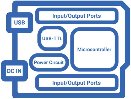
The above Arduino block diagram shows the important modules on an Arduino UNO board. When you think about the Arduino board the first image that comes to your mind might be that of an Arduino UNO or an Arduino Nano. That is because they are the most popular board among the community. That doesn’t mean the Arduino is limited to the capabilities of an ATMEGA328 chip. There are plenty of board variants available, with an entirely different set of features like different microcontrollers, layout, number of I/O ports, etc. We will take Arduino UNO as an example and will discuss each component in it.
Components on your Arduino UNO Board – What do they do?
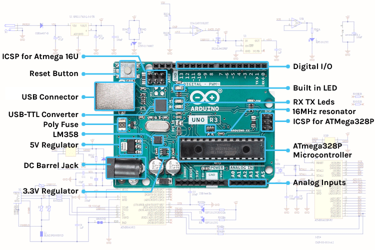
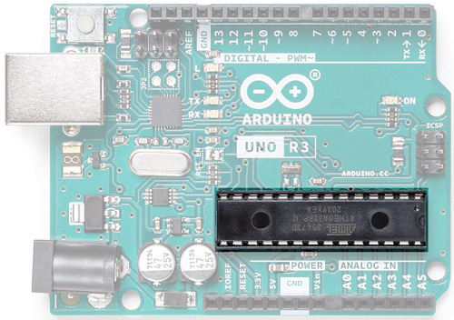
Let’s have a look at the basic parts or components of Arduino UNO. It will vary from board to board, depending on the Controller used and features. Here we will be looking at an Arduino Uno as an example. I have marked the main components/parts on a UNO in the image below.
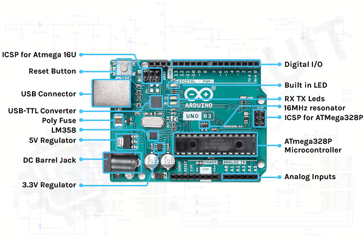
In the UNO board, the main component is the ATMega328P. It is the heart of the Arduino UNO. Near the MCU you can see a 16MHz resonator which will give the ATMega328P the clock signal to work. Near that, you can also see a connector named ICSP. It is used to burn the Arduino bootloader into the chip. And you can also see the header pins for the I/O.
If you look at the other side of the board, you can spot another microcontroller in a QFN package. It is an ATMega16U and is used as a USB -TTL converter. Near that, it will have its crystal and ICSP port to burn the firmware. There will be a reset button near it, which will reset the ATMega328P.
You can see the USB port and DC barrel jack on the left side. You can power the Arduino either through the USB port or the barrel jack. The barrel jack will accept a voltage range of 7-12V. And near the barrel jack, you can find two voltage regulators. One for 5V and one for 3.3V. Let’s check out each component.
USB - B Socket
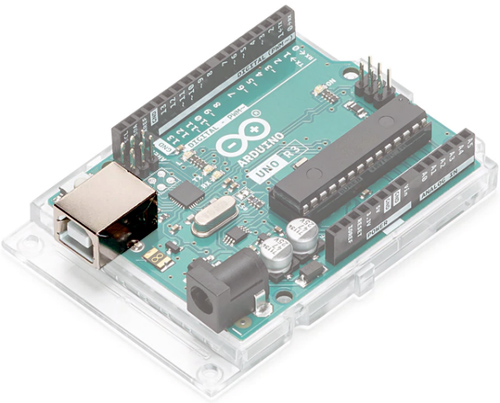
The USB socket on the UNO has two functions. One is for communication, to connect with the computer through a USB port, and also to load the firmware into the Arduino with the help of the bootloader. The second is to power the Arduino. You can use the USB port to power the Uno directly from any USB port.
ISCP Pins
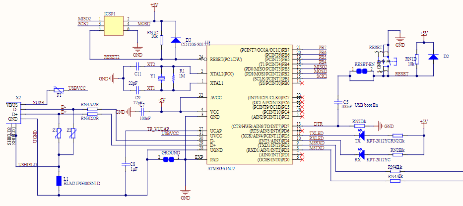
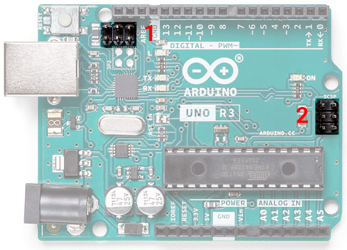
In the UNO you can find two 6 pin connectors. One is near the USB – TTL Chip and the other one is at the end of the board. These pins are used to program those two microcontrollers. The USB – TTL chip on this board is an ATMgega16U. The connector marked as 1 is used to program the USB-TTL firmware into this chip. And the connector marked as 2 is used to burn the bootloader into the ATMega328 microcontroller.
Reset Button
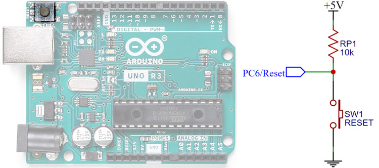
As the name indicates this tactile switch is used to reset the ATMega328 microcontroller. It’s connected to the PC6/Reset pin, which is pulled up through a 10K. When the switch is pressed the pin is pulled to the ground and the chip will reset.
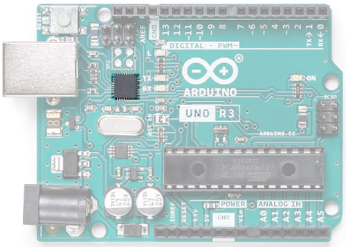
USB-TTL Interface Chip
To communicate with the computer, the Arduino relies on a USB-TTL interface. In UNO, ATMega16U with custom firmware act as a USB – TTL interface chip.
Crystal Oscillator/ Ceramic resonator
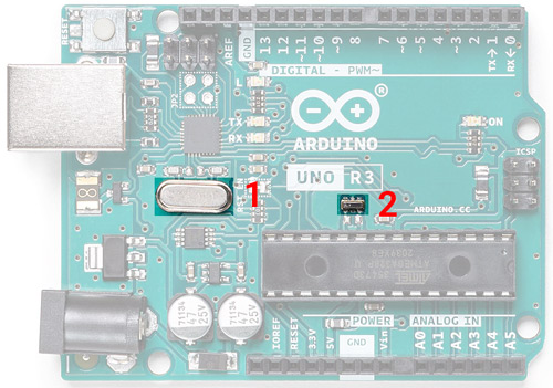
For a microcontroller to work it needs a clock source. The clock circuit determines the speed with which the microcontroller operates. How many instructions per second it will execute is dependent on the clock frequency. The ATMega series microcontrollers can use two types of clock sources. One is an internal RC oscillator that is already built into the microcontroller. But the drawback of using the internal oscillator is that its maximum frequency is limited and it is not that accurate. That is where the second option comes into place, i.e., using an external clock generator. In this case, we will be using a Quartz crystal oscillator or a ceramic resonator for this purpose. In the picture below, you can see two components are marked. The first one is a 16MHz crystal oscillator used for the ATMega16U2 chip and the second one is a 16MHz resonator used for the ATMega328P microcontroller.
Power Path control
If you inspect a UNO, you can find an LM358. You might think what’s its role here. It’s used as a comparator to control the input power path. When the input power is provided through the barrel jack or Vin pin the power path control circuit will cut off the USB power pin from the circuit which in fact will protect the USB port.
Voltage Regulator
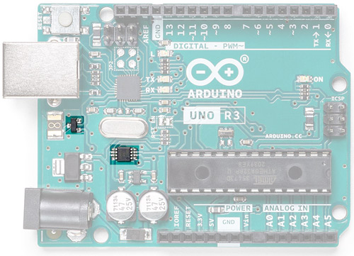
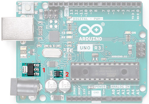
The ATMega328 and ATmega16U2 have a maximum input voltage of around 5V and most modules or accessories work on either 5V or 3.3V. The Arduino can accept 7-12V through the Vin pin or the DC barrel jack. So, to step it down, there are two regulators onboard. One is a 5V regulator (marked as 1) for the microcontrollers and the other one is a 3.3V regulator which is used to provide 3.3V through 3.3V pin.
DC Barrel Jack
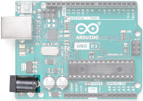
The DC barrel jack is used to supply power to the UNO. We can supply 7-12V through it and hence we can use a 12V DC adapter or 9V DC adapter on this Jack to power the Arduino board.
Digital and Analog I/O
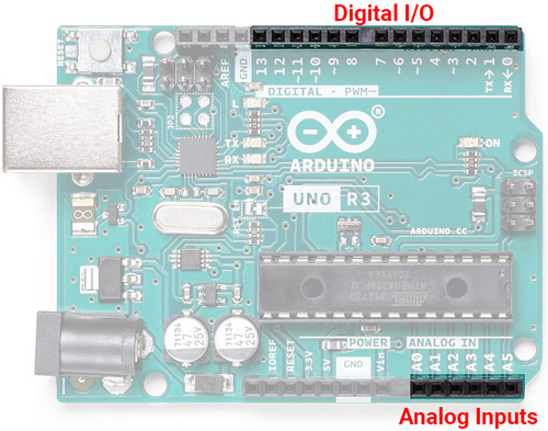
The Arduino UNO has 14 digital I/O pins and 6 Analog inputs. The digital I/O pins are 5V logic level and you can also use the Analog pins as digital I/O too. Arduino UNO supports 6 channel 10 bit ADC inputs through A0-A5, which can be sampled and analyzed using UNO.
Status LEDs and Inbuilt LED
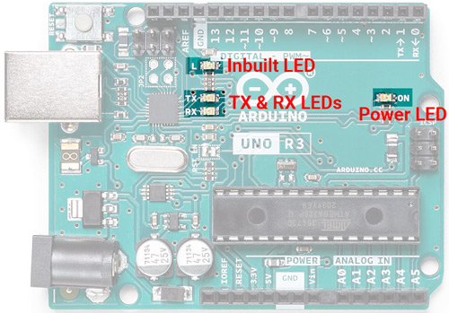
Uno has 4 LEDs onboard. One is used as a power indicator and two are used to show the activity of the Rx and Tx pin. The other one is tied to the Digital pin 13, which can be used to test the Arduino board or simply as an indicator.
ATMega328P – The Brain
Last but not least is the main component on the Arduino board – the ATMega328P Microcontroller. UNO uses a 28Pin DIP version of ATMega328P. Atmega328P is pre-programmed with a bootloader that allows you to directly upload the program to Arduino through USB without the need for an external programmer.
Arduino UNO Circuit Diagram
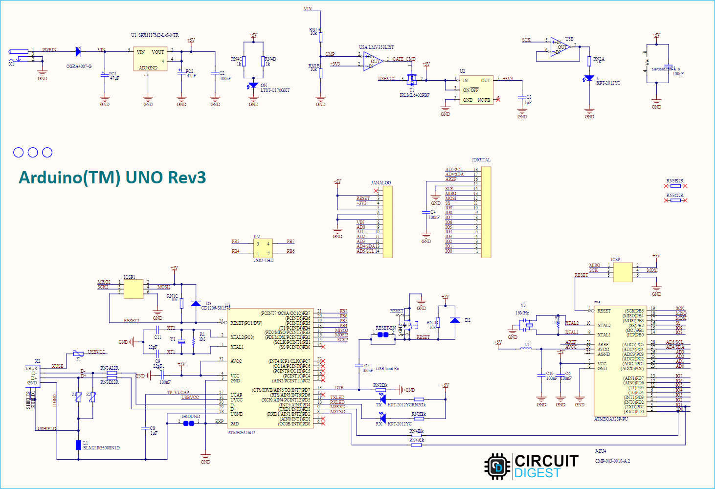
Now let’s have a look at the Arduino UNO Schematics. The below circuit diagram, clearly shows all how the various components are connected to design an Arduino UNO board.
Here is the power section of the circuit in which you can find the DC barrel jack for the power input, 5V, and 3.3V regulators, and the power path control circuit around the LM358 comparator circuit.
The 5V regulator is the NCP1117ST50T3G and the Vin of this regulator is connected via DC jack input through the M7 diode which acts as reverse polarity protection. The output of the 5V regulator is connected to the rest of the 5V net in the circuit and also to the input of the 3.3V regulator, LP2985-33DBVR.
Another source of 5V is the VCC pin of the USB which is connected to the drain of an FDN340P, a P-channel MOSFET, and the source is connected to the 5V net. The gate of the transistor is connected to the output of an LMV358 op-amp used as a comparator. The comparison is between 3V3 and Vin/2. When Vin/2 is larger, this will produce a high output from the comparator and the P-channel MOSFET is off. If there is no Vin applied, the V+ of the comparator is pulled down to GND and Vout is low, such that the transistor is on and the USB VCC is connected to 5V.
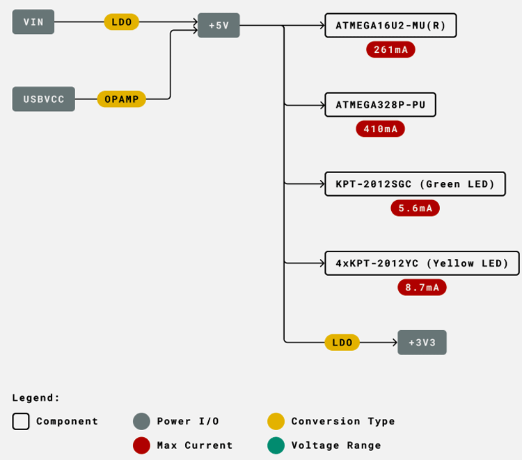
Here is the power tree view of Arduino UNO
Now let’s have look at the USB-TTL section. As we discussed earlier the main component in this is the ATMega16U2 microcontroller. From an electronic design perspective, this section is similar to the microcontroller section. This MCU has an ICSP header, an external crystal with load capacitors (CL), and a Vcc filter capacitor. Z1 and Z2 are varistors or VDRs and are used as ESD protection devices. And we can also find two resistors in series with the D+ and D- pin which is used for the proper termination impedance for the USB data lines.
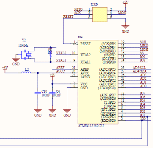
Now the main part of the schematics, which accommodates the ATMega328P microcontroller and its supplementary components.
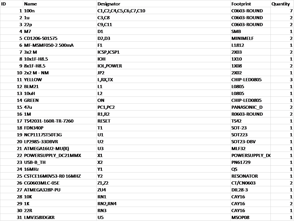
Arduino UNO Board- BOM
And here is the BOM for Arduino UNO R3. It contains all the component details along with its footprint and Quantity. This will come in very handy if you are building your own Arduino UNO Board.

