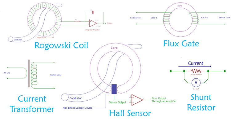
Current is a very critical factor in Electronics or Electrical Engineering. In electronics, current can have a bandwidth from few nano-amperes to hundreds of amperes. This range can be much wider in Electrical domain typically to several thousand amperes, especially in Power Grids. There are different methods to sense and measure current inside a circuit or a conductor. In this article, we will discuss how to measure current using various current sensing techniques with their advantages, disadvantages and applications.
Hall Effect Sensor Current Sensing Method
Hall Effect is discovered by the American physicist Edwin Herbert Hall and can be used to sense the current. It is generally used to detect magnetic field and can be useful in many applications like Speedometer, door alarm, DIY BLDC.
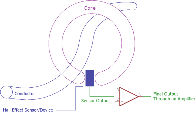
Hall Effect sensor produces an output voltage depending on the magnetic field. The ratio of the output voltage is proportional to the magnetic field. During the current sensing process, the current is measured by measuring the magnetic field. The output voltage is very low and needs to be amplified to a useful value by using a high gain amplifier with very low noise. Apart from amplifier circuit Hall Effect sensor requires additional circuitry as it is a linear transducer.
Pros:
- Can be used in higher frequency.
- Can be used in both AC and DC accurately.
- Noncontact based method.
- Can be used in a rough environment.
- It is reliable.
Cons:
- The sensor drifts and requires compensation.
- Additional circuit requires for useful output.
- Costly than shunt based technique.
Hall Effect sensors are used in clamp meters as well as in many Industrial and Automotive current sensing applications. Many types of linear Hall effect sensor can sense current from several mili-amps to thousands of amperes. Due to this, Smart Grid Monitoring Application also uses a different type of Hall effect sensor to monitor the conductor current.
Flux Gate Sensor Current Sensing Method
A saturable Inductor is the main component for the Fluxgate sensing technique. Due to this, Fluxgate sensor is called as Saturable Inductor Current Sensor. The inductor core which is used for the fluxgate sensor works in the saturation region. The saturation level of this inductor is highly sensitive and any internal or external flux density changes the saturation level of the inductor. The permeability of the core is directly proportional to the saturation level, hence the inductance also changes. This change in inductor value is analyzed by the flux gate sensor to sense the current. If the current is high, the inductance become lower, if the current is low, the inductance become high.
The Hall Effect sensor works similarly to the fluxgate sensor, but there is one difference between them. The difference is in the core material. Flux Gate sensor uses a saturable inductor but the Hall Effect sensor uses air core.
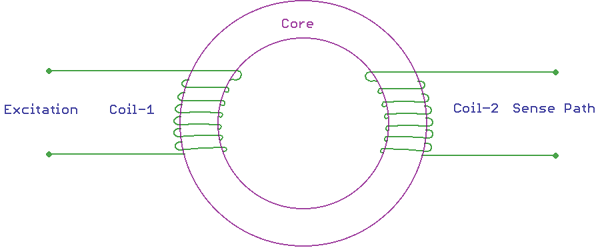
In the above image, the basic construction of a flux gate sensor is shown. There are two coils primary and secondary wrapped around a saturable inductor core. The changes in the current flow can alter the core permeability resulting in the change of inductance across the other coil.
Pros:
- Can measure in a wide range of frequency.
- Has great accuracy.
- Low offset and drifts.
Cons:
- High secondary power consumption
- A risk factor increases for voltage or current noise in the primary conductor.
- Only suitable for DC or low-frequency AC.
Fluxgate sensors are used in Solar Inverters to sense the current. Other than this, closed-loop AC and DC current measurement can be easily done by using Flux Gate sensors. Flux Gate current sensing method can also be used in Leakage current measurement, overcurrent detection etc.
Rogowski Coil Current Sensing Method
Rogowski coil is named after German physicist Walter Rogowski. The Rogowski coil is made using a helical shape air core coil and wrapped around the targeted conductor for current measurement.
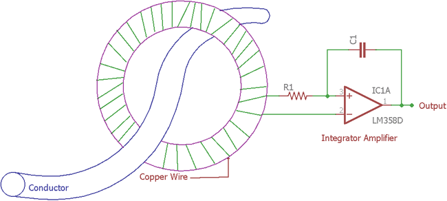
In the above image, the Rogowski coil is shown with additional circuitry. The Additional circuitry is an integrator circuit. Rogowski coil provides output voltage depending on the rate of current change in the conductor. An additional integrator circuit is required for making an output voltage which is proportional to the current.
Pros:
- It is a good method to detect fast high-frequency current change.
- Safe operation in terms of handling the secondary winding.
- Low-Cost solution.
- Flexibility in handling due to open loop construction.
- Temperature compensation is not complex.
Cons:
- Only suitable for AC
- Has low sensitivity than the current transformer.
Rogowski coil has a wide range of application. For example, measurement of current in large power modules, especially across the MOSFETs or High power transistors or across the IGBT. Rogowski coil provides flexible measuring option. As Rogowski coil response is very fast over transients or high-frequency sinusoidal waves, it is a good choice to measure high-frequency current transients in the power lines. In power distribution or in smart grid, Rogowski coil provides excellent flexibility for current measurements.
Current Transformer Current Sensing Method
Current transformer or CT is used to sense the current by secondary voltage which is proportional with the current in secondary coil. It is Industrial transformer that converts the large value of voltage or current into a much smaller value in its secondary coil. The measurement is taken across the secondary output.
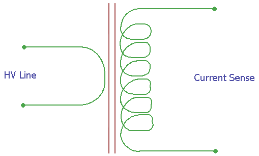
In the above image, the construction is shown. It is a ideal CT transformer with a primary and secondary ratio as 1:N. The N depends on the specifications of the transformer. Learn more about transformers here.
Pros:
- Large current handling capacity, more than the other methods shown in this article.
- Do not require additional circuitry.
Cons:
- Requires maintenance.
- Hysteresis occurs due to magnetization.
- High primary current saturates the ferrite core materials.
The main use of CT transformer based current sensing technique is in the Power grid due to very high current measurement capacity. Few clamp meters also use a current transformer for the measurement of Alternating current.
Shunt Resistor Current Sensing Method
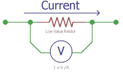
This is the most used method in current sensing techniques. This technique is based on Ohms law.
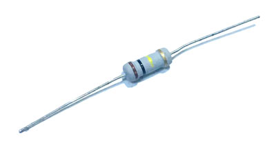
A low-value resistor in series is used to sense the current. When the current flow through a low-value resistor, it produces a voltage difference across the resistor.
Let's take an example.
Suppose 1A of current is flowing through a 1-ohm resistor. As per ohm's law Voltage is equivalent of current x resistance. Therefore, when 1A of current flow through a 1-ohm resistor, it will produce 1V across the resistor. The wattage of the resistor is a critical factor to be considered. However, there are very small value resistors also available in the market, where the resistance is in mili-ohms range. In such a case, the voltage difference across the resistor is also very small. A high gain amplifier is required to increase the amplitude of the voltage and finally, the current is measured using the reverse calculation basis.
An alternative approach for this type of current sensing technique is to use the PCB trace as shunt resistor. Since the copper trace of a PCB offer very small resistance, one can use the trace to measure the current. However, in such an alternative approach, several dependencies are also a huge concern to get an accurate result. The main game-changing factor is temperature drifting. Depending on the temperature, the trace resistance gets changed resulting in an error result. One needs to compensate for this error in the application.
Pros:
- Very cost effective solution
- Can work in AC and DC.
- Additional equipment not required.
Cons:
- Not suitable for higher current operation due to heat dissipation.
- Shunt measurement provides an unnecessary decrease in system efficiency due to the energy wastage across the resistor.
- Thermal drift provides error result in a high-temperature application.
The application of Shunt resistor includes digital amp meter. This is an accurate and cheaper method other than the Hall Effect sensor. The shunt resistor can also provide a low resistance path and allows an electric current to pass one point to the other point in a circuit.
How to select proper Current Sensing Method?
Selecting the proper method for current sensing is not a difficult thing. There are few factors need to be considered for choosing the right method, like:
- How much accuracy is needed?
- DC or AC measurement or both?
- How much power consumption is required?
- What is the current range and bandwidth to be measured?
- Costing.
Other than those, acceptable sensitivity and interference rejection are also need to be considered. As every factor can’t be satisfied, some trade-offs are made to compromise one feature with the other depending on the application requirement priority.


