Communication Interfaces are one of the factors that are considered when selecting a microcontroller to be used for a project. The designer ensures that the microcontroller being selected has all the interfaces required to communicate with all the other components to be used for the product. The existence of some of these interfaces like SPI and I2C on microcontroller invariably increases the cost of such microcontrollers, and depending on the BOM budget it may make a desired microcontroller not affordable. In situations like these the techniques like Bit Banging come in to play.
What is Bit Banging?
Bit banging is a technique for serial communication in which the whole communication process is handled via software instead of dedicated hardware. To transmit data, the technique involves the use of software to encode the data into signals and pulses which are used to manipulate the state of an I/O pin of a microcontroller which serves as the Tx pin to send data to the target device. To receive data, the technique involves sampling the state of the Rx pin after certain intervals which is determined by the communication baud rate. The software sets all the parameter needed to achieve this communication including synchronization, timing, levels etc., which are usually decided by dedicated hardware when bit banging is not used.

When to use Bit Banging
Bit-Banging is usually used in situations where a microcontroller with the required interface is not available or when switching to a microcontroller with the required interface might be too expensive. It thus provides a cheap way of enabling the same device to communicate using several protocols. A microcontroller which is previously enabled for UART communication only, can be equipped to communicate using SPI and 12C via bit banging.
Algorithm for Serial Communication via Bit Banging
While the code to implement bit banging may differ across diverse microcontrollers and may also vary for different serial protocols, but the procedure/algorithm for implementing bit banging is the same across all platforms.
To send data for instance the pseudo-code below is used;
- Start
- Send start bit
- Wait for timing to correspond with the baud rate of receiver
- Send data bit
- Wait for duration to correspond with the baud rate of receiver again
- Check if all data bits have been sent. If no, go to 4. If yes, goto 7
- Send stop bit
- Stop
Receiving data tends to be a little bit more complex, usually an interrupt is used to determine when data is available on the receiver pin. This helps ensure the microcontroller doesn’t waste too much processing power. Although certain implementations use any of the microcontrollers I/O pins but the chances of noise and errors, if not probably handled, is higher. The algorithm to receive data using interrupts is explained below.
- Start
- Enable interrupt on Rx pin
- When interrupt is triggered, obtain start bit
- Wait for timing according to the baud rate
- Read the Rx pin
- Repeat from 4 till all data has been received
- Wait for timing according to the baud rate
- Check for stop bit
- Stop
Bit Banging over SPI
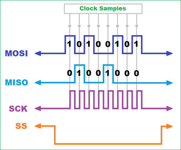
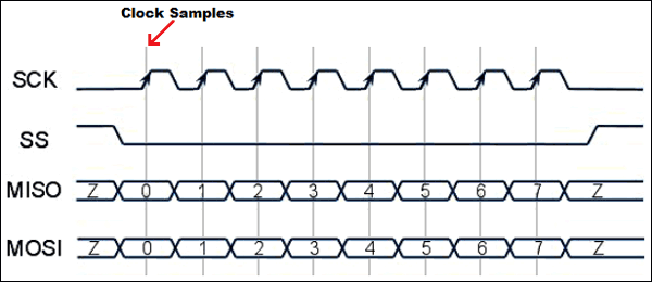
As mentioned above, bit banging for different protocols work differently and it’s thus important to read about each protocol, to understand data framing and clocking before attempting to implement. Taking the SPI mode 1 as an example, the base value of the clock is always 0 and data is always sent or received on the rising edge of the clock. The timing diagram for the SPI Mode 1 communication protocol is shown below.

To implement this, the following algorithm can be used;
- Start
- Set the SS pin low to begin communication
- Set the pin for Master Out Slave In (MOSI) to the first bit of the data to be sent
- Set the clock pin (SCK) high so data is transmitted by the master and received by the slave
- Read the state of the Master in Slave Out (MISO) to receive the first bit of data from slave
- Set SCK Low, so data can be sent on the next rising edge
- Go to 2 till all data bits have been transmitted.
- Set the SS pin High to stop transmission.
- Stop
Example of Bit Banging: SPI communication in Arduino
As an example, let’s implement the algorithm for SPI communication via bit banging in Arduino to show how data can be bit-banged over SPI using the code below.
We start by declaring the pins of the Arduino to be used.
const int SSPin = 11;
const int SCKPin = 10;
const int MISOPin = 9;
const int MOSIPin = 8;

byte sendData = 64;   // Value to be sent
byte slaveData = 0;  // for storing the  value sent by the slave
Next, we move to the void setup() function where the state of the pins are declared. Only the Master in Slave out (MISO) pin is declared as an input since it is the only pin that receives data. All other pins are declared as output. After declaring the pin modes, the SS pin is set to HIGH. The reason for this is to ensure the process is error free and communication only starts when it’s set to low.
void setup()
{
pinMode(MISOPin, INPUT);
 pinMode(SSPin, OUTPUT);
 pinMode(SCKPin, OUTPUT);
 pinMode(MOSIPin, OUTPUT);
digitalWrite(SSPin, HIGH);
}
Next, we start the loop to send data. Note that this loop will keep sending the data repeatedly.
We start the loop by writing the SS pin low, to initiate the beginning of communication, and call on the bitbangdata function which breaks the predefined data into bits and send. With this done, we then write the SS pin HIGH to indicate the end of data transmission.
void loop()
{
  digitalWrite(SSPin, LOW);        // SS low
  slaveData = bitBangData(sendData); // data transmission
  digitalWrite(SSPin, HIGH);       // SS high again
}
The bitbangdata() function is written below. The function takes in the data to be sent and breaks it down into bits and sends it over by looping over the code for the transmission as indicated in step 7 of the algorithm.
byte bitBangData(byte _send)  // This function transmit the data via bitbanging
{
  byte _receive = 0;

  for(int i=0; i<8; i++)  // 8 bits in a byte
  {
    digitalWrite(MOSIPin, bitRead(_send, i));    // Set MOSI
    digitalWrite(SCKPin, HIGH);                  // SCK high
    bitWrite(_receive, i, digitalRead(MISOPin)); // Capture MISO
    digitalWrite(SCKPin, LOW);                   // SCK low
  }
  return _receive;        // Return the received data
}
Disadvantages of Bit Banging
Adopting bit banging should however be a well thought out decision as there are several downsides to bit banging that may make it not reliable for implementation in certain solutions. Bit banging increase the power consumed by the microcontroller due to the high processing power consumed by the process. Compared to dedicated hardware, more communication errors like glitches and jitters occur when bit banging is used especially when data communication is being performed by the microcontroller at the same time as other tasks. Communication via bit banging happens at a fraction of the speed with which it occurs when dedicated hardware is used. This may be important in certain applications and may make bit banging a “not so good” choice.
Bit banging is used for all kinds of serial communications including; RS-232, Asynchronous Serial Communication, UART, SPI, and I2C.
UART via Bit banging in Arduino
One of the popular implementations of bit banging is the Arduino Software Serial library which enables the Arduino to communicate over UART without using the dedicated hardware UART pins (D0 and D1). This gives a lot of flexibility as users can connect as many serial devices as the number of pins on the Arduino board can support.


