When you are designing and producing a product, a PCB can easily become one of the most costly components of the whole product, thus lowering the PCB cost can be one of the major factors that can be proven beneficial for lowering the overall production cost. Majorly, the PCB cost can be reduced by cutting the PCB size as well as selecting the proper components, and introducing proper design techniques. This is why in this article, we will describe the most common PCB cost reduction techniques which you can implement when designing and fabricating your PCB. In our previous PCB articles, we have discussed many PCB design techniques like:
- Efficient Placing of Thermal Vias Improve Heat Management
- Via Stitching in PCB Design
- Understanding Blind, Buried, and Through-hole vias in PCB
- How can Teardrops help in Improving Quality and Stability of your PCB Design
You can check those out if you are interested to learn about PCB design and manufacturing. That being said, let's look into the tips to reduce PCB manufacturing costs.
Reducing the Size of the PCB
Reduction of PCB Size is the most common PCB cost-cutting technique that can be used to lower the PCB cost. There is another positive outcome as the reduction of PCB size also leads to the reduction in the size of the product, which is again fruitful for different kinds of applications. In previous times, through-hole components were the widely available components that directly affected the size of the PCB.
Today, all components can be converted to SMD versions, even ICs, as different manufacturers provide different packages that are smaller in size that could be useful to directly reduce the PCB size. See the below images to understand how component sizes reduce the board dramatically.
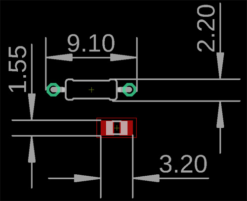
In the above images, we can see the difference between a through-hole and SMD 0805 package size difference. Now, it's really clear that the same value same wattage resistors can be used in a much smaller space. You can even place two resistors, one in the top layer other in the bottom layer. There is a much smaller size also available other than 0805, such as 0603, 0402, 0201, etc. This is the same thing that is reflected in capacitors, diodes, inductors. A simple electronics circuit uses maximum resistors and capacitor-type components that even reducing these two could reduce the board size by at least 30-40%.
Other ways to reduce component size on PCB:
The SMD resistors can even be reduced furthermore by applying proper design and component selection technique, see the below resistors.
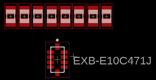
8 and 0805 Resistor vs Resistor SIP package 8 pin. It is just like a chess game where you need to make the right decisions and it is the right move to reduce the PCB size. The SMD components are also relatively cheaper than the through-hole one, both component cost-wise and in assembly-related cases. Well, again, there is a reason for that as through-hole components require additional steps to cut the component leads and to solder the same in the board.
Reducing unnecessary Layers as well as bad Layer Specifications
Almost all the time, people add unnecessary layer counts for different reasons such as Thermal compensations, bad routing experiences, and so on. A lot of money can be saved during the fabrication of the circuit board if layer counts are reduced from 6 layers to 4 layers, 4 layers to 2 layers, and so on. One of the important things to keep in mind is the ways to reduce the board layer count whenever it is possible. However, for complex boards that include ball packages or extensive routings, it is essential to have a higher layer count, which may be necessary for better signal quality and the circuit board’s overall performance. In such cases, the increased cost is better to save additional rework money, thus it is important to take the right decision about how many layers one should use to make a circuit board design.
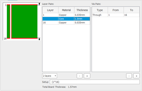
Another common mistake that designers make is providing bad layer specifications to the vendor, resulting in high PCB costs during production. Does your design need 70um copper thickness in all layers? Is it possible to make the board in 17.50um on both the Top and Bottom layer as well as making 35um in the inner layers or vice versa? It will reduce a lot of costs during production. Also, please specify the proper creepage distance for your PCB.
Reducing PCB Cost by changing PCB Materials
Material cost becomes a major factor when it comes to choosing the right material. In most cases, you can get away with generic FR4 PCB, but there are some instances where FR4 PCBs will not hold. A good example will be “PCBs for LED” I am referring to the type you will find in an LED bulb.
PCB Material:
Costing can be reduced by selecting the right board materials. In many cases and many different applications, the standard FR-4 Board is everything that will do the job where choosing a more expensive option will not make any difference and can be termed as a luxury. The temperature grade can be standard 130-140 degrees, which can be useful in all cases until or unless there is a special requirement.
PCB Thickness:
PCB cost increases for nonstandard PCB thickness. 1.6mm is the standard PCB thickness. Increasing or decreasing the PCB thickness will attract more money to be spent during the production phase.
Solder Mask and Legend Color:
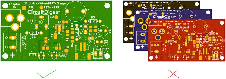
Also, try to use a green solder mask without making fancy colored PCBs such as Black, Red, and Blue, etc. Those are expansive color options and incur a lot of cost on PCB making. The Green Solder mask is widely used in the PCB manufacturing process and it is the cheapest option for PCBs. This rule applies to the Legend Color as well. The most common legend color is white. Choosing another color such as Black will increase the cost of PCB production heavily. This theory applies to most manufacturers, but some manufacturers charge the same price for all the different solder masks and silkscreen options.
Surface Finish:
Using Immersion Gold/ENIG for unnecessary reasons is a bad choice that incurs PCB costs. It is required for high-speed, impedance-controlled traces to lock the signal integrity correctly. Do you need this to be done on any simple boards? Immersion Tin or HAL(Sn-Pb) can be used to reduce the cost of production.
Routing related compensation
Adding Buried and Blind Vias incurs a large cost during the PCB manufacturing process. Changing the design in a certain way that it could be routed in a way where the Buried or Blind Vias are not required. Also, sometimes, making the routing easier, people place components in a certain order that during the assembly process they are forced to solder the component manually. It is not a cost-effective option.
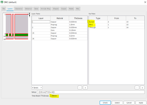
Believe me, in almost all cases, a good design practice could reduce the chance of using buried or blind Vias until it is a truly dense board that requires signal integrity where buried or blind Vias are required.
Adjust order volume and lead time
Last but not least component, assembly, or manufacturing PCBs, order volume is a major thing to reduce production cost. It is inversely proportional to the price. In general, PCB manufacturing cost is less expensive when the order volume becomes higher. It is possible to plan and adjust the order volume as per the selected PCB manufacturer that can fulfill your order volume. Always compare the prices of the required PCs with the required quantity in the future. But, make sure that the board is well tested during the POC (Proof of Concept) phase and the design is finalized for production. Making an order without testing the PCB is a waste of time, as well as a huge amount of money is involved.
Now, you need to know the lead time. Order the PCBs when you are not in a hurry and have a perfect goal set with time-related compensation before starting a production project. Different vendors have different lead time-related rules. The PCB cost gets very high if you order the PCB with a very short lead time. So, always adjust the lead time to have a minimum cost quotation on the PCBs. For bulk production, saving a few bucks may not be anything for a single board, but it could make a huge impact in higher volume quantities.
Have any other technique that can help users in reducing PCB manufacturing costs? Share with us in the Circuit Digest Forum.


The price of PCB is cheap, it does not mean the quality is not good, you can try PCBpartner online pcb order.