From large power stations to compact SMPS circuits, transformers can be found almost everywhere. Though there are many types of transformers and their exact working differs based on the application, the basic working of the Transformer remains the same. When we examine a schematic with a transformer in it, we might have noticed “dot” like symbols placed on one end of the transformer windings. These symbols are placed according to the dot convention rule. But what is it? And what purpose does it serve?
What is Dot Convention?
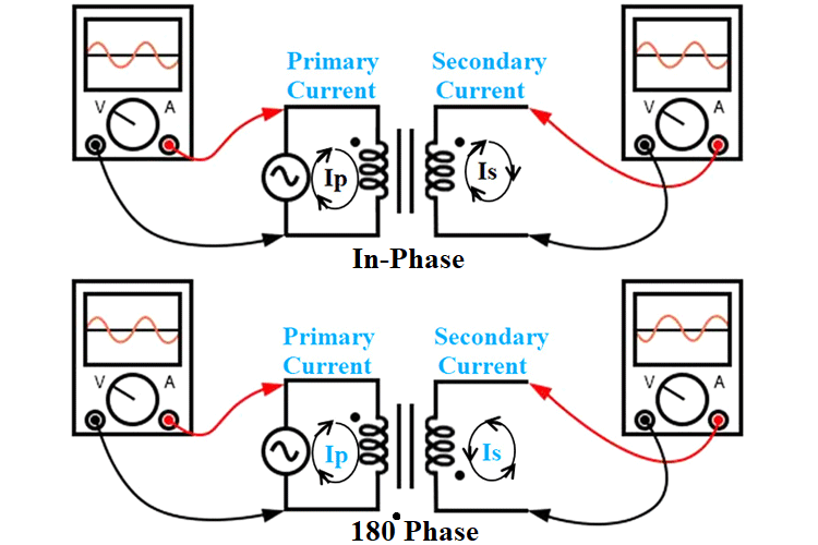
The Dot convention is a type of polarity marking for transformer windings showing which end of the winding is which, in relation to the other windings. It is used to indicate phase relationships in transformer schematic diagrams and it involves the placement of dots on top of the primary and secondary terminals as shown below.

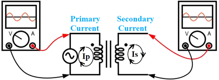
When the dots are placed next to the top ends of the primary and secondary windings as shown below, it indicates that the polarity of the instantaneous voltage across the primary winding will be the same as that across the secondary winding. Meaning the phase shift between the primary and secondary winding will be zero (in- Phase), and the direction of the Secondary current (Is) and Primary current (Ip) will be the same.

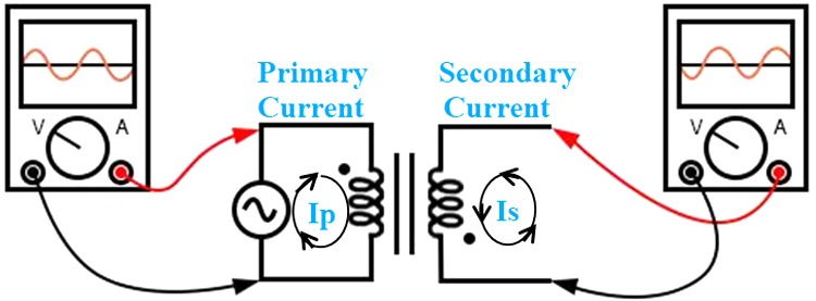
However, if the dots are placed in reversed positions (e.g. up on primary, down on secondary or vice versa), like the image below, It indicates that the primary and secondary current and voltages are 180° out of phase and the primary and secondary currents (IP and IS) will be in opposite in direction to one another.

With the knowledge of this convention and the polarity of the transformer, the engineers now have their destiny in their hands, and can decide to reverse the phase relationships in whichever way they want by changing which end of their circuit is connected to the transformer’s terminals. For instance, for the out-of-phase transformer example above, by switching how the terminals are connected like the image below, the secondary side is made in-phase with the primary.

Why is Dot Convention Important?
In the study of transformers, it is generally assumed (at least for resistive loads) that the Voltage and Current are in phase for the secondary and primary windings. This assumption is usually based on the belief that the secondary winding and the primary winding of the transformer are done in the same direction. The phase relation between primary and secondary currents and voltages depends on how each winding is wrapped around the core, hence if the winding is wrapped around the core in the same direction as shown below; then the voltage and current on both sides should be in phase.

However, this assumption is not always correct, as the direction of the windings could be opposite (as shown in the image above), which will mean if connection is to the same terminals, then the voltage in the secondary winding (VS) will be out-of-phase and the direction of the current (Is) is in opposite direction to the primary current.
This phase loss, and inverse polarity, however trivial it sounds, creates serious problems in power system protection, measurement, and control systems. As an example, reversing the polarity in an instrument transformer winding, for instance, may defeat protective relays, lead to inaccurate power and energy measurements, or result in the display of negative power factor during measurements. It could also lead to an effective short circuit in parallel transformer windings, and in signal circuits, can lead to incorrect operation of amplifiers and speaker systems, or cancellation of signals that are meant to add.
Since transformers are not transparent, it is impossible to know which way to connect a circuit to it to get an in-phase (or out-of-phase) voltage and current, thus, to mitigate the risks associated with reverse polarity connection and phase loss, and provide a way of identifying the polarity of the windings, transformer manufacturers came up with a polarity indication standard called; the “Dot Convention”.
Alphanumeric Labels in Transformers
Asides the dot convention, another polarity indication technique used in transformers is the Alphanumeric labels, which are typically made up of the “H” and “X” along with subscript numbers which represent winding polarity. The “1” wires (H1 and X1) represent where the polarity-marking dots would normally be placed. A typical transformer with the alphanumeric label is shown below.


