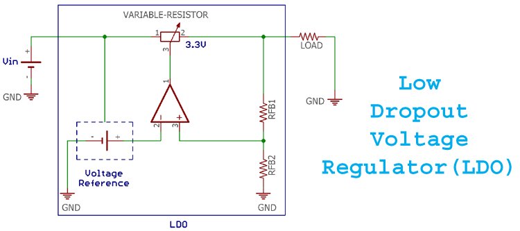
Today, electronic devices have shrunken in size than ever before. This enables us to pack in tones of features in compact portable devices like smart watches, fitness trackers, and other wearable devices, it also helps us to deploy remote IoT devices for cattle monitoring, asset tracking etc. One common thing among all these portable devices is that they are battery operated. And when a device is battery operated it is important for design engineers to select components that conserve every milli-volt in their design to run the device for a longer time with the available battery juice. Once such component is the Low-Dropout Voltage Regulator (LDO). In this article we will learn more about LDO and how to select the right one for your circuit design.
What is a Regulator in electronics?
A regulator is a device or a well-designed mechanism that regulates something, here the something usually refers to voltage of current. There are two types of regulators mainly used in electronics, the first one is switching regulator and the second one is the linear regulator. They both have a different working architecture and subsystem, but we wont be discussing them in this article. But to put it simple, if a regulator is controlling the output current then it is called a current regulator. By the same aspect, voltage regulators are used to controlling the voltage.
Difference between LDO and Linear Regulators
Linear regulators are the most common devices used for power supply regulation and most of us will be familier with devices like 7805, LM317. But, the downside of using a Linear Regulator in battery operated applications is that here the input voltage of a linear regulator is always needed to be higher than the regulated output voltage. Meaning, the differences between the input voltages and the output voltage is high. Therefore, standard linear regulators have some limitations when the regulated output voltage is required to be a close value of the input voltage.
Working of an LDO
LDO is a part of linear regulator dynasty. But, unlike normal Linear regulators, in an LDO the difference between the input voltage and the output voltage is less. This difference is called as dropout voltage. Since the LDO has very low dropout voltage it is called as Low dropout voltage regulators. You can think of a LDO’s an a linear resistor palced in series with the load to reduce the voltage to required level. The advandage of a having an LDO is that the voltage drop across it will be far less than a resistor.
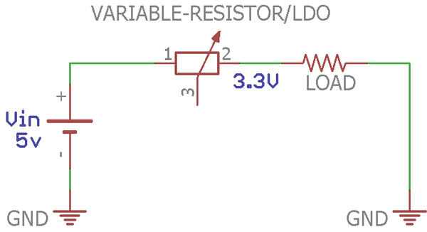
Since the LDO offers low dropout voltage between input and output, it can work even if the input voltage is relatively close to the output voltage. The voltage drop across an LDO will be between 300mV to 1.5V maximum. In some LDOs, the voltage differences are even less than 300mV.
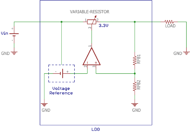
The above image is showing a simple LDO construction where a closed-loop system is designed. A reference voltage is created from the input voltage and fed to a differential amplifier. The output voltage is sensed by a voltage divider and again fed to the input pin of the differential amplifier. Depending on these two values, the output from the reference voltage and output from the voltage divider, the amplifier produces output. This output controls the variable resistor. Hence, anyone value of this two could alter the output of the amplifier. Here the voltage reference is needed to be stable to accurately sense the other. When the reference voltage is stable, a small variation of the output voltage reflects on the input of the differential amplifier via the resistor divider. The amplifier then controls the variable resistor to provide a stable output. On the other hand, the voltage reference is not dependent on the input voltage and provides stable reference across the differential amplifier making it immune to the transient changes and also makes the output voltage independent of the input voltage. The variable resistor shown here will normally be replaced by an efficient MOSFET or JFET in the actuall construction. Bipolar transistors are not used in LDOs due to the extra requirements of current and heat generation which leads to poor efficiency.
Parameters to consider while selecting your LDO
Basic Features
As it is an essential device to ensure proper power delivery to the load, the first key feature is the load regulation and the stable output. Proper load regulation is essential during load current changes. When the load increase or decrease it's current consumption the output voltage from the regulator should not fluctuate. The fluctuation of the output voltage is measured in mV range per ampere of current and called as accuracies. The output voltage accuracy of an LDO ranges from 5mV to 50mV range, a few percentages of the output voltage.
Safety and Protection Features
LDO offers basic safety features by ensuring proper power delivery across the output. The safety features are accommodated using protection circuitry across input and output. The protection circuits are Under-voltage Protection (UVLO), Over-voltage Protection (OVLO), Surge protection, output short-circuit protection and thermal protection.
In some situations, the input voltage provided to the regulator might drop significantly low or increase to high value. This results in improper voltage and current output from the LDO which will damage our load. If the input voltage across the LDO is beyond the limits, the UVLO and OVLO protection are triggered to protect the LDO and the load. The lower limit for UVLO and the maximum input voltage limits can be set using simple voltage dividers.
Surge protection circuit offers immunities to the LDO from transients and high voltage surges or spikes. It is also an additional feature offered by different LDOs. Output short circuit protection is a form of overcurrent protection. If the load gets shorted the short circuit protection feature of an LDO disconnects the load from the input power supply. Thermal protection works when the LDO gets heated. During heat-up operation, the thermal protection circuit stops the LDO from working to prevent any further damage to it.
Additional Features
LDOs can have two additional logic level control pin to communicate with a microcontroller input. Enable pin often referred to as EN and this is an input pin of the LDO. A simple microcontroller can change the state of EN pin of an LDO to enable or disable the power output. This is a handy feature when loads need to be turned on or off for application purposes.
Power Good pin is an output pin from the LDO. This pin can also be connected with a microcontroller unit to provide a logic low or high depending on the power condition. Based on the state of power good pin, microcontroller unit can get the information about the power status across the LDO.
Limitations of LDO
Although LDO offers proper output at low dropout voltage, still it has some limitations. The major limitation of the LDO is efficiency. It is true that the LDO is better than the standard linear regulators in terms of power dissipation and efficiency but it is still a poor choice for the portable battery-related operations where the efficiency is the main concern. The efficiency gets even poor if the input voltage is significantly higher than the output voltage. The heat dissipation increases when the voltage drop is higher. The excess waste energy which is transformed as heat and requires a heatsink, resulted in increased PCB area as well as incurring a component cost. For better efficiency, switching regulators are still the best choice over linear regulators especially LDOs.
Should I use LDO for my next design?
As LDOs offer very low dropout voltage, it is good to select an LDO only when the desired output voltage is very close to the available input voltage. Below questions can help you determine if you circuit design actually needs an LDO
- Is the desired output voltage is close to the available input voltage? If yes, then how much? It is good to use LDO if the difference between Input voltage and output voltage is less than 300mV
- Is 50-60% of efficiency is accepted for the desired application?
- Low noise power supply is a need?
- If the cost is a problem and simple, lower part count, the space-saving solution is needed.
- Will it be too expensive and bulky to add a switching circuit?
If you have answered “YES” for all the above question, then LDO might be a good choice. But, what will be the specification of the LDO? Well, it depends on the below parameters.
- Output Voltage.
- Minimum and Maximum Input voltage.
- Output current.
- Package of the LDOs.
- The cost and availability.
- Enable and Disable option is required or not.
- Additional protection options those are required for the application. Such as Over current protection, UVLO, and OVLO, etc.
Popular LDOs in the market
Every single power IC manufacturer like Texas Instruments, Linear Technology etc.also has some solutions for LDO. Texas Instruments has wide range of LDOs depending on various design needs, the below chart shows its huge collection of LDO with a wide range of output current and input voltage.
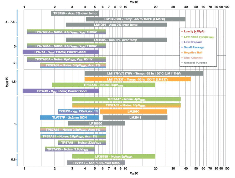
Similarly, Linear technology, from Analog devices also has some high performance Low Dropout Regulators.
LDO – Example Design
Lets consider a practical case in which LDO will be mandatory. Suppose a low cost, simple, space-saving solution is needed for converting the 3.7V lithium battery output to a stable 3.3V 500mA source with short current limit and thermal protection. The power solution needs to be connected with a microcontroller to enable or disable some load and the efficiency can be 50-60%. Since we need a simple and low cost solution we can rule out the switching regulator designs.
A lithium battery can provide 4.2V during full charge condition and 3.2V on fully empty condition. Therefore, the LDO can be controlled to disconnect the load at low voltage situation by sensing the input voltage of the LDO by the microcontroller unit.
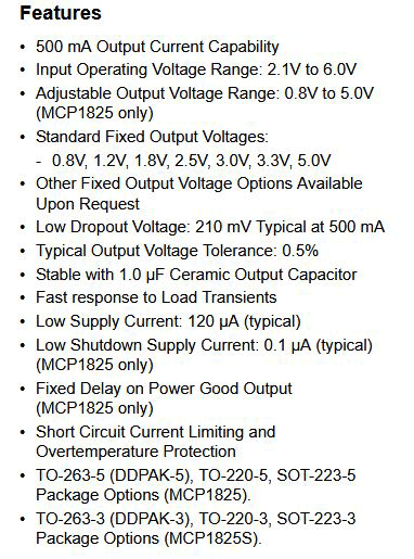
To sumerize we need, 3.3V output voltage, 500mA of current, Enable pin option, low part counts, around 300-400 mV dropout requirements, output short circuit protection along with thermal shutdown feature, for this application my personal choice of LDO is MCP1825 - 3.3V fixed voltage regulator by microchip.
The full feature list can be seen in the below image, taken from the datasheet -
Below is the circuit diagram of MCP1825 along with the pin-out. The schematic is also provided in the datasheet, thus by simply connecting few external components like resistor and capacitor we can easily use our LDO to regulate out required voltage with minimum voltage dorp.

LDO - PCB design guidelines
Once you have deicided the LDO and tested it to work for your design, you can proceed with designing the PCB for your circuit. The following are the few tips you should remember while designing a PCB for LDO components.
- If SMD package is used, it is essential to provide a proper copper area in PCBs since LDOs dissipate heats.
- Copper thickness is a major contributor to trouble-free operation. 2 Oz (70um) copper thickness will be a good choice.
- C1 and C2 need to be as close as possible to the MCP1825.
- The thick ground plane is required for noise-related issues.
- Use Vias for proper heat dissipation in double-sided PCBs.


