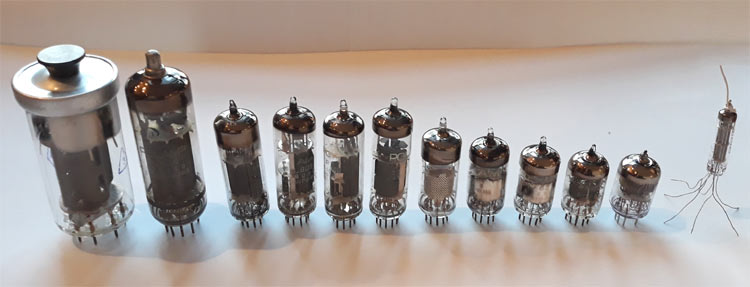
You might be tempted to dismiss the good old tube as a relic of the past – after all, how can a few pieces of metal in a glorified light bulb hold up to the transistors and integrated circuits of today? Although tubes lost their place in the storefront of consumer electronics but they still remain insignificant use where there is need for a lot of power at very high (GHz range) frequencies, such as in radio and television broadcasting, industrial heating, microwave ovens, satellite communications, particle accelerators, radar, electromagnetic weapons plus a few applications requiring lower power levels and frequencies, such as radiation meters, X-ray machines and audiophile amplifiers.
20 years ago most displays used a vacuum picture tube. Did you know that there might be a few tubes lurking around your house too? In the heart of your microwave oven lays, or rather sits in a socket, a magnetron tube. Its job is to generate high power and high-frequency RF signals that are used to heat whatever you put in the oven. A different household device with a tube inside is the old CRT TV that now most likely sits in a cardboard box in the attic after being replaced with a new flat-screen TV. The CRT stands for “Cathode-ray Tube” - those tubes are used to display the received video signal. They are quite heavy, big and inefficient when compared to LCD’s or LED displays, but they did get the job done before the other technologies came into the picture. It is a good idea to learn about them because so much of the modern world still relies on them, most TV transmitters use vacuum tubes as their power output device, because they are more efficient at high frequencies than transistors. Without magnetron vacuum tubes cheap microwave ovens wouldn’t exist, because semiconductor alternatives were only recently invented and remain expensive. A lot of circuits such as oscillators, amplifiers, mixers etc. are easier to explain with tubes and see how they work, because classic tubes, especially triodes, are extremely easy to bias with few components and calculate their amplification factor, bias etc.
How Vacuum Tubes Work?
Regular vacuum tubes work based on a phenomenon called thermionic emission, also known as the Edison effect. Imagine that it’s a hot summer day you are waiting in line in a stuffy room, next to a wall with a heater along the length of it, some other people are waiting in line too and someone turns on heating, people start moving away from the heater – then someone opens the window and lets a cold breeze in, causing everyone to migrate to it. When thermionic emission occurs in a vacuum tube, the wall with the heater is the cathode, heated by a filament, the people are the electrons and the window is the anode. In most vacuum tubes the cylindrical cathode is heated by a filament (not too different from the one in a light bulb), causing the cathode to emit negative electrons that are attracted by a positively charged anode, causing an electric current to flow into the anode and out of the cathode (remember, current goes into the opposite direction than electrons).
Below we are explaining the evolution of Vacuum tube: Diode, Triode, Tetrode and Pentode along with some special types of Vacuume tubes like Magnetron, CRT, X-ray Tube etc
In the beginning there were Diodes
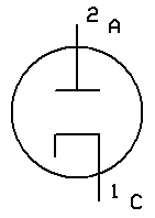
This is utilized in the simplest vacuum tube – the diode, consisting of the filament, the cathode and the anode. Electric current flows through the filament in the middle, causing it to heat up, glow and emit thermal radiation – similar to a light bulb. The heated filament heats the surrounding cylindrical cathode up, giving enough energy to the electrons to overcome the work function, causing a cloud of electrons called a space charge region, to form around the heated cathode. The positively charged anode attracts electrons from the space charge region causing a flow of electric current in the tube, but what would happen if the anode was negative? As you know from your high school physics lessons like charges repel – the negative anode repels electrons and no current flows, this is all happening in a vacuum, because air impedes electron flow. This is how a diode is used to rectify AC.
Nothing like the good old Triode!
In 1906 an American Engineer called Lee de Forest discovered that adding a grid, called a control grid, between the anode and the cathode allows for the anode current to be controlled. Triode’s construction is similar to the diode, with the grid being made from very fine mobyldenium wire. The control is achieved by biasing the grid with a voltage – the voltage usually being negative in respect to the cathode. The more the voltage is negative, the lower the current. When the grid is negative it repels electrons, decreasing the anode current, if it is positive more anode current flows, at a cost of the grid becoming a tiny anode, causing grid current to form which might damage the tube.
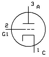
Triode and other “gridded” tubes are usually biased by connecting a high value resistor between grid and ground, and a lower value resistor between the cathode and ground. The current flowing through the tube causes a voltage drop on the cathode resistor, increasing the cathode voltage in respect to ground. The grid is negative in respect to the cathode, because the cathode is at a higher potential than the ground to which the grid is connected to.
Triodes and other regular tubes can be used as switches, amplifiers, a mixers and there is a lot of other uses to choose from. It can amplify signals by applying the signal to the grid and letting it steer the anode current, if a resistor is added between the anode and the power supply the amplified signal can be taken out of the anode voltage, because anode resistor and the tube act similar to a voltage divider, with the triode part varying its resistance in accordance to the input signal’s voltage.
Tetrodes to the rescue!
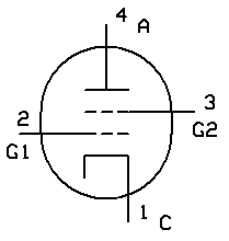
Early triode suffered from low gain and high parasitic capacitances. In the 1920s it was found that putting a second (screen) grid between the first one and the anode, increased the gain and lowered parasitic capacitances, the new tube was named tetrode, meaning in Greek four (tetra) way (ode, suffix). The new tetrode wasn’t perfect, it suffered from negative resistance caused by secondary emission that could cause parasitic oscillations. Secondary emission occurred when the second grid voltage was higher than the anode voltage, causing a decline in anode current with the electrons hitting the anode and knocking out other electrons and the electrons being attracted by the positive screen grid, causing an additional possibly damaging increase in grid current.
Pentodes – the final frontier?
Research in ways of reducing secondary emission resulted in the invention of the pentode in 1926 by the Dutch engineers Bernhard D.H. Tellegen and Gilles Holst. It was found that adding a third grid, called a suppressor grid, between the screen grid and the anode, removes the effects of secondary emission by repelling electrons knocked out of the anode back to the anode since it is either connected to ground or to the cathode. Today pentodes are used in transmitters below 50MHz, as tetrodes in transmitters work good up to 500MHz and triodes up to the gigahertz range, not to mention audiophile use.
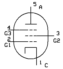
Different Types of Vacuum Tubes
Apart from these “regular” tubes there is a lot of specialized industrial and commercial tubes designed for different uses.
Magnetron
The magnetron is similar to the diode, but with resonant cavities shaped into the tube’s anode and the whole tube located between two powerful magnets. When voltage is applied, the tube starts oscillation, the electrons passing the cavities on the anode, causing generation of radio frequency signals, in a process similar to whistling.
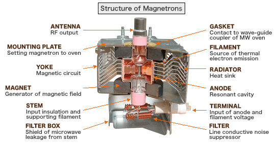
X-ray Tubes
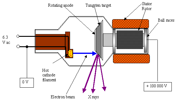
X-ray tubes are used to generate X-rays for medical or research purposes. When a high enough voltage is applied to the vacuum tube diode X-rays are be emitted, the higher the voltage the shorter the wavelength. To deal with heating of the anode, caused by electrons hitting it, the disc-shaped anode rotates, so the electrons hit different parts of the anode during its rotation, improving cooling.
CRT or Cathode-Ray Tube
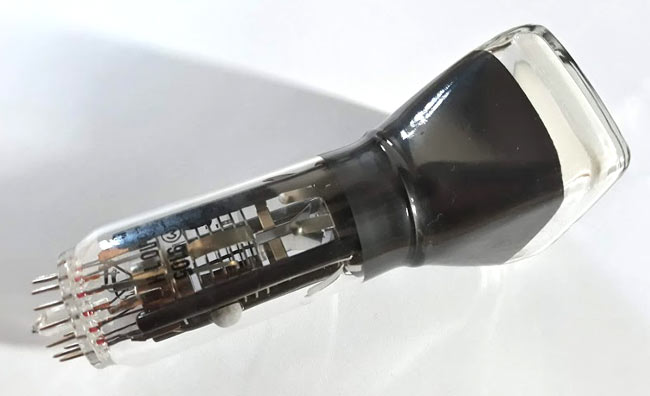
The CRT or the “Cathode-ray Tube” was the main display technology back in the day. In a monochromatic CRT a hot cathode or a filament acting as a cathode emits electrons. On their way to the anodes they pass through small hole in the Wehnelt cylinder, the cylinder acting as a control grid for the tube and helping to focus the electrons into a tight beam. Later they are attracted and focused by several high voltage anodes. This part of the tube (cathode, Wehnelt cylinder and the anodes) is called an electron gun. After passing the anodes they pass the deflection plates and impact the fluorescent front of the tube, causing a bright spot to appear where the beam hits. The deflection plates are used to scan the beam across the screen by attracting and repelling electrons in their direction, there are two pairs of them, one for the X-axis and one for the Y-axis.
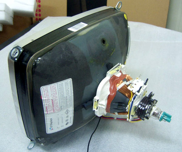
A small CRT made for oscilloscopes, you can clearly see (from the left) the Wehnelt cylinder, the circular anodes and the deflection plates in the shape of the letter Y.
Traveling-wave Tube
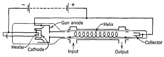
Traveling-wave tubes are used as RF power amplifiers on board communication satellites and other spacecraft due to their small size, low weight and efficiency at high frequencies. Just like the CRT it has an electron gun in the back. A coil called a “helix” is wound around the electron beam, the input of the tube is connected to the end of the helix closer to the electron gun and the output is taken from the other end. The radio wave flowing through the helix interacts with the electron beam, slowing and speeding it up in different points, causing amplification. The helix is surrounded by beam focusing magnets and a attenuator in the middle, it’s purpose is to prevent the amplified signal from getting back to the input and causing parasitic oscillations. At the end of the tube a collector is located, it being comparable to the anode of a triode or pentode but no output is taken from it, is located. The electron beam impacts the collector, ending it’s story inside the tube.
Geiger–Müller tubes
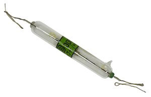
Geiger–Müller tubes are used in radiation meters, they consist of a metal cylinder (cathode) with a hole on one end and a copper wire in the middle (anode) inside a glass envelope filled with a special gas. Whenever a particle passes through the hole and impacts the wall of the cathode for a brief moment the gas in the tube ionises, allowing current to flow. This impulse can be heard on the meter’s speaker as a characteristic click!


