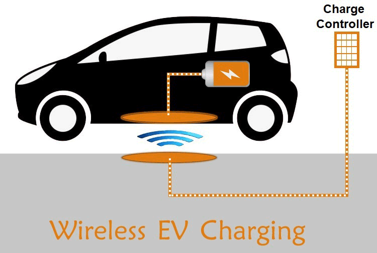
Now a days world is shifting towards electrified mobility to reduce the pollutant emissions caused by nonrenewable fossil fueled vehicles and to provide the alternative to pricey fuel for transportation. But for electric vehicles, traveling range and charging process are the two major issues affecting it’s adoption over conventional vehicles.
With the introduction of Wire charging technology, no more waiting at charging stations for hours, now get your vehicle charged by just parking it on parking spot or by parking at your garage or even while driving you can charge your electric vehicle. As of now, we are very much familiar with wireless transmission of data, audio and video signals so why can’t we transfer power over the Air.
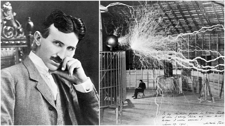
Thanks to great scientist Nikola Tesla for his limitless amazing inventions in which wireless power transfer is one of them. He started his experiment on wireless power transmission in 1891 and developed Tesla coil. In 1901 with the primary goal to develop a new wireless power transmission system Tesla started developing the Wardenclyffe Tower for large high-voltage wireless energy transmission station. The saddest part is to satisfy Tesla's debts, the tower was dynamited and demolished for scrap on July 4th 1917
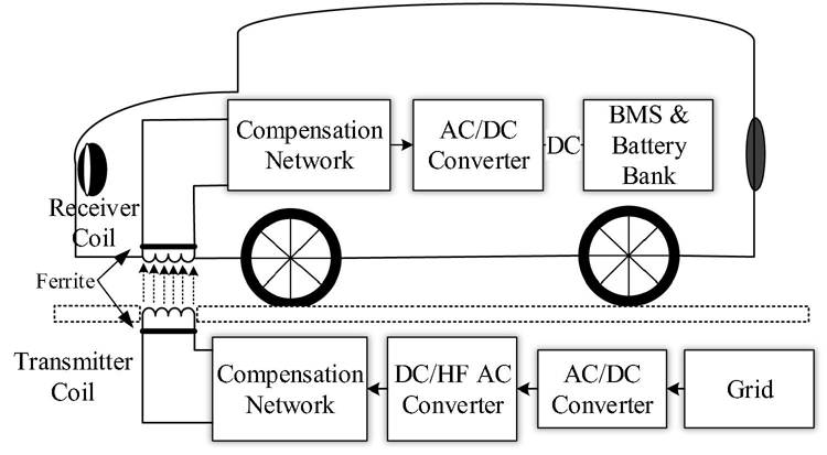
Basic principle of wireless charging is same as transformer working principle. In wireless charging there are transmitter and receiver, 220V 50Hz AC supply is converted into High frequency alternating current and this high frequency AC is supplied to transmitter coil, then it creates alternating magnetic field that cuts the receiver coil and causes the production of AC power output in receiver coil. But the important thing for efficient wireless charging is to maintain the resonance frequency between transmitter and receiver. To maintain the resonant frequencies, compensation networks are added at both sides. Then finally, this AC power at receiver side rectified to DC and fed to the battery through Battery Management System (BMS).
Static and Dynamic Wireless Charging
Based on the application, Wireless charging systems for EV can be distinguished into two categories,
- Static Wireless Charging
- Dynamic Wireless Charging
1. Static Wireless Charging
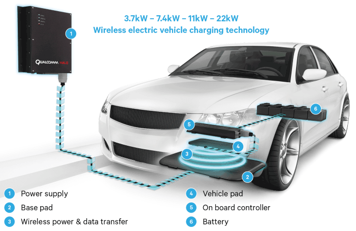
As the name indicates, the vehicle gets charged when it remains static. So here we could simply park the EV at the parking spot or in garage which is incorporated with WCS. Transmitter is fitted underneath the ground and receiver is arranged in vehicle’s underneath. To charge the vehicle align the transmitter and receiver and leave it for charging. The charging time depends on the AC supply power level, distance between the transmitter & receiver and their pad sizes.
This SWCS is best to build in areas where EV is being parked for a certain time interval.
2. Dynamic Wireless Charging System (DWCS):
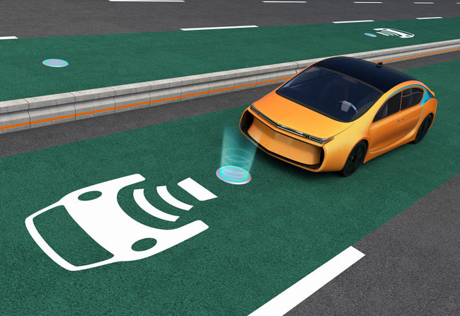
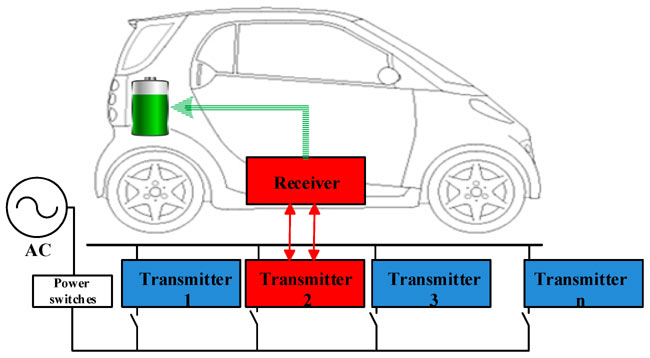
As the name indicates here vehicle get charged while in motion. The power transfers over the air from a stationary transmitter to the receiver coil in a moving vehicle. By using DWCS EV's travelling range could be improved with the continuous charging of its battery while driving on roadways and highways. It reduces the need for large energy storage which further reduce the weight of the vehicle.
Types of EVWCS
Based on operating Techniques EVWCS can be classified into four types
- Capacitive Wireless Charging System (CWCS)
- Permanent Magnetic Gear Wireless Charging System (PMWC)
- Inductive Wireless Charging System (IWC)
- Resonant Inductive Wireless Charging System (RIWC)
1. Capacitive Wireless Charging System (CWCS)
Wireless transfer of energy between transmitter and receiver is accomplished by means of displacement current caused by the variation of electric field. Instead of magnets or coils as transmitter and receiver, coupling capacitors are used here for wireless transmission of power. The AC voltage first supplied to power factor correction circuit to improve efficiency and to maintain the voltage levels and to reduce the losses while transmitting the power. Then it is supplied to an H-bridge for the High-frequency AC voltage generation and this high frequency AC is applied to transmitting plate which causes the development of oscillating electric field that causes displacement current at receiver plate by means of electro static induction.
The AC Voltage at receiver side is converted to DC to feed the battery through BMS by rectifier and filter circuits. Frequency, voltage, size of coupling capacitors and air-gap between transmitter and receiver affects the amount of power transferred. It’s operating frequency is between 100 to 600 KHz.
2. Permanent Magnet Gear Wireless Charging System (PMWC)
Here transmitter and receiver each consist of armature winding and synchronized permanent magnets inside the winding. At transmitter side operation is similar to motor operation. When we apply the AC current to transmitter winding it induces mechanical torque on transmitter magnet causes it's rotation. Due to the magnetic interaction change in transmitter, PM field causes torque on receiver PM which results it's rotation in synchronous with transmitter magnet. Now change in receiver permanent magnetic field causes the AC current production in winding i.e, receiver acts as generator as mechanical power input to the receiver PM converted into electrical output at receiver winding. The coupling of rotating permanent magnets is referred as magnetic gear. The generated AC power at receiver side fed to the battery after rectifying and filtering through power converters.
3. Inductive Wireless Charging System (IWC)
The basic principle of IWC is Faraday's law of induction. Here wireless transmission of power is achieved by mutual induction of magnetic field between transmitter and receiver coil. When the main AC supply applied to the transmitter coil, it creates AC magnetic field that passes through receiver coil and this magnetic field moves electrons in receiver coil causes AC power output. This AC output is rectified and filtered to Charge the EV’s energy storage system. The amount of power transferred depends on frequency, mutual inductance and distance between transmitter and receiver coil. Operating frequency of IWC is between 19 to 50 KHz.
4. Resonant Inductive Wireless Charging System (RIWC)
Basically resonators having high Quality factor transmit energy at much higher rate, so by operating at resonance, even with weaker magnetic fields we can transmit the same amount of power as in IWC. The power can be transferred to long distances without wires. Max transfer of power over the air happens when the transmitter and receiver coils are tuned i.e., both coils resonant frequencies should be matched. So to get good resonant frequencies, additional compensation networks in the series and parallel combinations are added to the transmitter and receiver coils. This additional compensation networks along with improvement in resonant frequency also reduces the additional losses. Operating frequency of RIWC is between 10 to 150 KHz.
Wireless Electric Vehicle Charging Standards
Wireless charging makes EV to charge without any need of plug in. If every company makes its own standards for wireless charging systems that won’t compatible with other systems then it won’t be a good thing. So to make wireless EV charging more user friendly Many international organizations like International Electro Technical Commission (IEC), the Society of Automotive Engineers
(SAE), Underwriters Laboratories (UL) Institute of Electrical and Electronics Engineers (IEEE) are working on standards.
- SAE J2954 defines WPT for Light-Duty Plug-In EVs and Alignment Methodology. According to this standard, level 1 offers maximum input power of 3.7 Kw, level2 offers 7.7Kw, level 3 offers 11Kw and level4 offers 22Kw. And the minimum target efficiency must be greater than 85% when aligned. Allowable ground clearance should be up to 10 inches and side to side tolerance is upto 4 inches. The most preferable alignment method is magnetic triangulation that assists to stay within charge range in manual parking and assists to find parking spots for autonomous vehicles.
- SAE J1772 standard defines EV/PHEV Conductive Charge Coupler.
- SAE J2847/6 standard defines Communication Between Wireless Charged Vehicles and Wireless EV Chargers.
- SAE J1773 standard defines EV Inductively Coupled Charging.
- SAE J2836/6 standard defines Use Cases for Wireless Charging Communication for PEV.
- UL subject 2750 defines Outline of Investigation, for WEVCS.
- IEC 61980-1 Cor.1 Ed.1.0 defines EV WPT Systems General Requirements.
- IEC 62827-2 Ed.1.0 defines WPT-Management: Multiple Device Control Management.
- IEC 63028 Ed.1.0 defines WPT-Air Fuel Alliance Resonant Baseline System Specification.
Companies Currently Developed and Working on WCS
- Evatran group's making Plugless Charging for passenger EVs like Tesla Model S, BMW i3, Nissan Leaf, Gen 1 Chevrolet Volt.
- WiTricy Corporation is making WCS for Passenger cars and SUVs till now it is working with Honda Motor Co. Ltd, Nissan, GM, Hyundai, Furukawa Electric.
- Qualcomm Halo is making WCS for Passenger, sport and race car and it is acquired by Witricity corporation.
- Hevo Power is making WCS for Passenger car
- Bombardier Primove is making WCS for Passenger car to SUVs.
- Siemens and BMW is making WCS for Passenger car.
- Momentum Dynamic is making WCS Corporation Commercial fleet and Bus.
- Conductix-Wampfler is making WCS for Industry fleet and Bus.
Challenges Faced by WEVCS
- To install static and dynamic wireless charging stations on the roads, new infrastructure development is required as current arrangement are not suitable for the installations.
- Need to maintain the EMC, EMI and frequencies as per standards for the human Health and safety concern.


