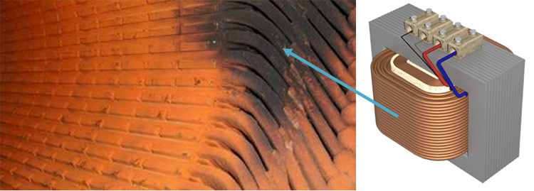
Have you experienced Motors or Transformers failing or Burning out in your plant without giving any warning signs during running, If yes then it is time to include a Routine Electrical Signature Analysis Maintenance for your Motor or Transformer. Motor current signature analysis (MCSA) has proven to be a highly valuable predictive maintenance tool. In this case study, I will explain more on MCSA and how we use it during our maintenance schedule.
What is Electrical Signature Analysis Or Motor Current Signature Analysis?
Electrical Signature Analysis (ESA) is a diagnostic and analysis technique that is being used to analyze Motors, Generators, Transformers, and other Electric Equipment. This new technology has the ability to test operating electrical equipment and identify a variety of mechanical and electrical problems. ESA traces can be used to analyze the driven load with its power supply and perform inrush testing on motors. As a preventative maintenance tool, ESA can be used to perform a one-time test or periodic testing to track and record equipment performance. ESA is remote, non-intrusive and is invisible to the equipment being monitored!
ESA is used to evaluate rotors, stators, and Rotor – Stator Air Gap Conditions in electric motors. This is one of its prime uses. In many cases, a one-time test can be used to determine if problems are present in the motor. Current and Voltage data are acquired directly from the Motor Control Center (MCC) while the equipment is in operation. The collected data is then used to determine phase imbalance, motor load, power factor, power harmonics and the impact of the driven equipment on the motor. Rotor bar, as well as stator health and rotor-stator eccentricity (air gap) characteristics, are also assessed. In addition, degraded bearings can also be observed from the traces. ESA is particularly helpful in accessing mechanical conditions when it is not possible or convenient to make vibration measurements.
When an electric motor drives a mechanical system, it experiences variations in load caused by gears, pulleys, friction, bearings and other conditions that may change over the life of the motor. The variations in load caused by each of these factors, in turn, cause a variation in the current supplied to the motor. These variations modulate the carrier frequency. This testing Equipment utilizes a unique process to demodulate the signal from the carrier and present an unambiguous spectral display. Using normal and demodulated data permits analysis of not only the motor but also the load and the supplied power.
The Electrical Signature analysis indicates:
- Rotor bar deterioration
- Rotor eccentricity
- Stator phase imbalance
- Motor speed & slip
- Gear & belt imperfections
- Average running current, an indicator of motor torque
- Stroke time on assemblies with defined start & stop points
- Torsional vibration & dynamic loading
- Bearing degradation
- Changing friction forces
- Detects the Early Stages of Rotor Bar Failures in Induction Motors
- Saves Time and Precludes Plant breakdowns by Monitoring Plant Motors and Driven machinery from a Central Motor Control Center
- Permits Data Acquisition and Analysis from Multiple Sources –
- Accelerometers
- Proximity Probes
- Process Measurements
- AC Induction Motors
- DC Motors
- Generators & Transformers
About the Author
 Avinash Singh is an Electrical Engineer with over 11 years of rich experience in Electrical Maintenance, Installation, Testing, and Commissioning of all major Electrical equipments. He is specialized in bringing down Energy Cost of a Plant by reducing electricity bills and increasing energy efficiency. He also reduces plant breakdown cost by implementing proper maintenance activities during routine and shutdown. Through these Case Studies he shares his experience and challenges faced in his work routine with the readers of Circuit Digest.


