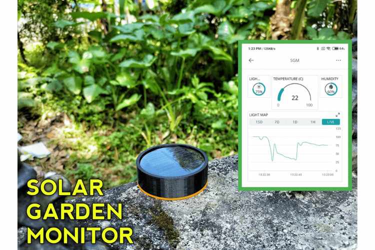
Our beloved plants and crops are very important to us. To get more yield it's necessary to maintain the optimum temperature, humidity and light in your garden/greenhouse. So in this article, I am going to explain how you can build a weather monitor for your garden/greenhouse. With the help of this weather monitor you can monitor the temperature, humidity and temperature through your smartphone/PC. This device is solar powered so you don't want to worry about the battery. Now let's see how you can make one yourself.
Theory and Working
The idea is to read the environmental parameters like temperature, humidity and light. Then using a microcontroller the data will uploaded to a cloud service and we can monitor that data from anywhere in the world. Here my plan is to use the esp12e as the microcontroller because it has lots of pins for our application and also it has wifi capability. I used Arduino iot cloud for remote monitoring because Arduino iot cloud is very simple to use and 100% free.
Components Used
- ADP1706ARDZ-3.3-R7(3.3V regulator) - 1
- LTC4054ES5-4.2(li-ion Battery Charging Module) -1
- ESP12E-1
- LDR-1
- DHT11-1
- LED -1
- 10K Resistor-1
- 330ohm Resistor-1
- 2K Resistor-1
- 10uf Capacitor-2
- 100nf Capacitor-1
- 3.7v li-ion battery-1
- 5v 80mA Solar panel-1
- ESP12E breakout board-1
- 8pin SOIC breakout board-1
- 2pin JST connector-2
I bought the regulator and battery charging module from Digikey.in. All other components I purchased from the local market.
Circuit Diagram
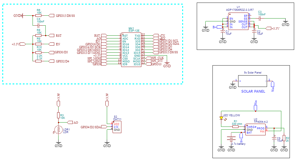
Here is the circuit diagram. The working of this circuit is very simple. The DHT 11 sensor and light sensor are connected to the ESP12E. microcontroller reads the sensor data and uploads it to the Arduino iot cloud. The Li-ion battery charges from the voltage of the solar panel. Then the regulator converts the 3.7v to 3.3v and feeds to the microcontroller. As I mentioned earlier the main component of this circuit is the ESP12E I have connected the necessary components for the working of ESP12E. Also in the case of the voltage regulator and charging IC I have connected the necessary components. I connected the light-dependent resistor to the A0 pin of ESP12E and connected the DHT11 to the D2 pin of ESP12E.
Building the Circuit
Most of the components used in this circuit are SMD. So I used a breakout board for the SMD components. I used readymade breakout boards for ESP12E and the regulator. And I made a simple breakout for the li. Ion charger IC since there is no breakout available for that IC. Then I soldered all components on a common PCB. I used female header pins for ESP12E, Voltage regulator and charging module. Then I added 2 JST connectors for the Solar panel and battery.
Arduino IoT Could Setup
Now go to Arduino IoT cloud and log in with your email ID. We need to create a thing on iot cloud for that Click on thing and click create. Then name the thing here I named a solar garden monitor.
Then click on add cloud variables. Here we need to add the variables to store our data. In our case, we need to store light intensity, temperature and humidity. So first I click on add variable and name the variable then select
the int variable for storing the light intensity value. And finally, click on add variable. In the same way, I have added two float variables for temperature and humidity.
The next step is to set the device. So click on select the device and click on setup new device then select third-party device because we are using esp12e.
Next, let's set up the network credentials. Just give your SSID and password to the wifi and copy the secret key.
Now let's set up the dashboard. Go to the dashboard and click on create dashboard then name the dashboard. Now click on Add and select the percentage widget. You can name the widget here. Now click on the link variable and select the previously created int variable and that's it. Do the same for humidity and temperature. I have also added a chart widget to display the live graph of light intensity. After adding widgets we can arrange for a PC view and a mobile phone view.
Programming
#include "thingProperties.h"
#include "DHT.h"
int sensor = A0;
int value;
#define DHTPIN 2
#define DHTTYPE DHT11
DHT dht(DHTPIN, DHTTYPE);
void setup() {
  pinMode(2,INPUT);
  dht.begin();
  initProperties();
  ArduinoCloud.begin(ArduinoIoTPreferredConnection);
  setDebugMessageLevel(2);
  ArduinoCloud.printDebugInfo();
}

void loop() {
  ArduinoCloud.update();
  humidity = 60;
  temperature = 22;
  value=analogRead(sensor);
  light=map(value,200,1024,0,100);
}
In the sketch tab you can see the sketch that is automatically generated by Arduino so click on it. Most of the code is already done by Arduino itself. We just need to add some details.
First I added the DHT library. then I defined the pins for dht sensor. In the setup section I declared the pins as input and started the communication.
In the loop section, we are reading the temperature and humidity using DHT commands and updating the Arduino cloud. In the case of light intensity we are using analog read so the values changes from 0-1024. To convert tht into 0-100 I used map function. That’s all about the coding. Now let's upload the code to nodemcu. Either you can use Arduino online editor or you can use normal Arduino ide to upload code.
If you are not installed the DHT library. Then just install the DHT library from library section. If you are using offline IDE then go to sketch – include library- manage library then search and install the library.
3D Designing and Printing the Enclosure

To enclose everything safely and securely I have designed an enclosure in tinkercad. The 3d design has 3 parts top side, the bottom side and the adaptor for placing the system in the garden. After designing I printed the model using my Ender 3v2 3D printer.
Final Assembly
After finishing the circuit soldering and 3D printing I placed the solar panel on the top side and the PCB on the bottom side and finally enclosed everything.
Testing the Project
After connecting to the wifi the ESP12E will start to upload data to the cloud. You can access it through a smartphone application or you can directly from the Arduino iot dashboard. To see data on your smartphone you have to download and install the Arduino iot remote.
Aditional Files
You can download the IoT-based Solar Powered Garden Project files using the given link. The links consists of circuit diagram, code and 3D model files which you can use to build your own Smart Garden monitoring system.
#include "thingProperties.h"
#include "DHT.h"
int sensor = A0;
int value;
#define DHTPIN 2
#define DHTTYPE DHT11
DHT dht(DHTPIN, DHTTYPE);
void setup() {
pinMode(2,INPUT);
dht.begin();
initProperties();
ArduinoCloud.begin(ArduinoIoTPreferredConnection);
setDebugMessageLevel(2);
ArduinoCloud.printDebugInfo();
}
void loop() {
ArduinoCloud.update();
humidity = 60;
temperature = 22;
value=analogRead(sensor);
light=map(value,200,1024,0,100);
}

