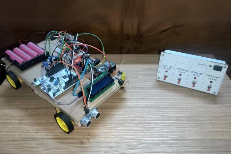
Vehicle Speed Control for Safety using RF Technology. In a world where road safety is a top priority, we’re here to introduce an innovative solution. Unlike regular speed detectors, which simply identify instances of excessive speed, this system uses advanced RF sensors and intelligent control technology. It not only detects speeding but also takes immediate action by wirelessly communicating with the vehicle's onboard systems to automatically regulate its speed. We harness cutting-edge RF technology, to enhance road safety significantly. The technical aspects of our RF-based system and its potential is to revolutionize transportation safety.
Over speeding, which means driving too fast, is a significant factor in 55.9% of road accidents worldwide. In the United States, more than half of deadly accidents happen because of over speeding. It's a similar situation in the European Union, where about more than 50% of accidents are due to overspeeding. In countries like India, where roads can be tricky, speeding leads to around more than 60% of road accidents. These numbers show that over speeding is a major problem globally, and we really need solutions like our Vehicle Over Speed Control system to make roads safer for everyone.
Working
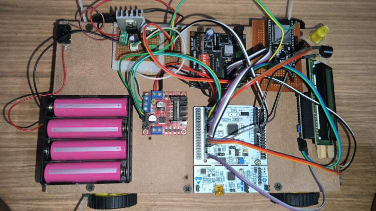
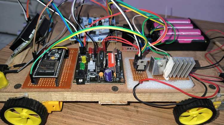
- In this project, I have used STM32NUCLEO development board and Radio Frequency (RF) technology to enhance road safety by controlling vehicle speed.
- A radio frequency transmitter is placed alongside the road to send data signals to approaching vehicles.
- When a vehicle, whether a car or a truck, enters the transmitter's range, it receives data containing a suggested speed limit.
Vehicle Speed Analysis
- Our system starts by analyzing the vehicle's current speed.
- If the vehicle's speed exceeds the suggested limit, the system takes immediate action.
- It alerts the driver visually, displaying an overspeeding warning on the vehicle's display.
Speed Control Mechanism
- Our system continually monitors the vehicle's speed, ensuring compliance with the suggested limit.
- If the vehicle exceeds the limit, it proactively alerts the driver through visual displays, indicating over speeding. Additionally, voice assistance is employed to audibly notify the driver.
Driver Response Time
- We understand that drivers may need some time to adjust their speed.
- Our system provides a window for the driver to slow down and adhere to the speed limit.
- This proactive approach encourages responsible driving.
Automatic Speed Reduction
- In cases where the driver doesn't reduce speed voluntarily, our system takes over.
- It automatically adjusts the vehicle's speed to match the suggested limit, which could be any value, such as 60 km/h.
- This ensures that the vehicle stays within safe speed limits.
Acceleration Control
- Beyond the suggested speed limit, the system restricts the accelerator's functionality.
- The driver can only accelerate up to the speed limit but cannot exceed it.
- This restriction prevents the driver from using the accelerator to surpass safe speeds.
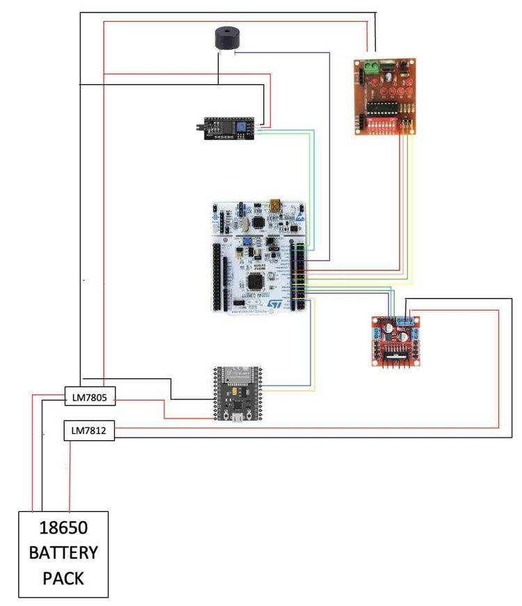
Circuit Diagram
Note: The STM32 Nucleo Board and the ESP32 board were purchased from digikey to meet the world energy challenge 2023 qualification requirements.
Advantages of the System
Prevention of Accidents:
- By actively monitoring and controlling vehicle speeds, the system helps prevent accidents caused by overspeeding. Immediate intervention ensures that drivers adhere to speed limits, reducing the likelihood of collisions.
Lives Saved:
- The system's ability to enforce speed limits promptly contributes to saving lives. Accidents at high speeds are more likely to result in severe injuries or fatalities, and the system acts as a proactive measure to mitigate these outcomes.
Reduced Severity of Injuries:
- In the event of an accident, the reduced speeds facilitated by the system can significantly decrease the severity of injuries. Lower speeds result in less force upon impact, reducing the risk of life-threatening injuries.
Economic Savings:
- Road accidents, especially those involving overspeeding, result in substantial economic costs related to medical expenses, vehicle repairs, and loss of productivity. The system helps minimize these costs by preventing accidents and their associated damages.
Insurance Cost Reduction:
- With fewer accidents and lower severity, the system can contribute to a reduction in insurance costs for both individuals and fleet operators. The improved safety record of vehicles equipped with this system may lead to lower insurance premiums.
Promotion of Responsible Driving Behavior:
- By actively notifying drivers about overspeeding and enforcing speed limits, the system encourages responsible driving behavior. This not only enhances individual safety but also contributes to a culture of compliance with traffic regulations.
Enhanced Road User Confidence:
- The presence of an effective overspeed detection and control system instills confidence in road users, including pedestrians and cyclists. Knowing that measures are in place to address overspeeding contributes to an overall sense of safety on the roads.
Environmental Impact:
- The system's ability to enforce speed limits can contribute to reduced fuel consumption and emissions. Consistent speeds within recommended limits optimize fuel efficiency and promote environmentally friendly driving habits.

STM32 NUCLEO64 CODE
#include <Wire.h>
#include <LiquidCrystal_I2C.h>
#include <SoftwareSerial.h>
SoftwareSerial mySerial(2, 3); // RX, TX on Nucleo-64
LiquidCrystal_I2C lcd(0x27,16,2);
const int trigPin = 11;
const int echoPin = 12;
int in1=6;
int in2=4;
int en1=5;
int buzzer_output=13;
int input7=7;
int input8=8;
int input9=9;
int input10=10;
int pulse = 100;
int pulse_LCD = 70;
boolean pulseChange = false;
int balanced_velocity=30;
float OBSTICLE_DISTANCE=20.0;
void setup()
{
   Serial.begin(115200); // Initialize serial communication
   mySerial.begin(115200);
   pinMode(trigPin, OUTPUT);
   pinMode(echoPin, INPUT);
   pinMode(13,OUTPUT);
   digitalWrite(13, LOW);
   pinMode(6,OUTPUT);
   pinMode(4,OUTPUT);
   pinMode(3,OUTPUT);
   digitalWrite(in1,HIGH);
   digitalWrite(in2, LOW);
   pinMode(5,OUTPUT);
   digitalWrite(buzzer_output,LOW);
   pinMode(input7,INPUT);
   pinMode(input8,INPUT);
   pinMode(input9,INPUT);
   pinMode(input10,INPUT);
   digitalWrite(in1,HIGH);
   digitalWrite(in2, LOW);
    lcd.init();
    lcd.backlight();
    lcd.setCursor(0,0);
    lcd.print("VEHICLE_OVERSPED");
    lcd.setCursor(2,1);
    lcd.print("DETECTION_AND");
    delay(2000);
    lcd.clear();
    lcd.setCursor(0,0);
    lcd.print("AUTOMATIC_SPEED");
    lcd.setCursor(1,1);
    lcd.print("CONTROL_SYSTEM");
    delay(2000);
    lcd.clear();
    lcd.setCursor(7,0);
    lcd.print("BY::");
    lcd.setCursor(1,1);
    lcd.print("KRITARTH JAIN");
    delay(2000);
    lcd.clear();
    }
    void loop()
 {
  digitalWrite(trigPin, LOW);
  delayMicroseconds(2);
  digitalWrite(trigPin, HIGH);
  delayMicroseconds(10);
  digitalWrite(trigPin, LOW);
  // Read the echo pulse duration in microseconds
  long duration = pulseIn(echoPin, HIGH);
  delayMicroseconds(10);
  // Calculate the distance in centimeters (in this example)
  float distance_cm = duration / 58.2;
  if (digitalRead(input7) == HIGH && distance_cm >= OBSTICLE_DISTANCE)  {
  Serial.println("input pin 7 is high");
  //speed limit 75 (for 40 KM/h)
  if(pulse>70){
  pulse =  70;
  pulseChange = true; //trigger buzzzer and limit speed
  Serial.println("speed limit 75 triggered");
  }
  if(pulse-balanced_velocity > 0){
  pulse_LCD = pulse-balanced_velocity; //40
  }
  }
  else if (digitalRead(input8) == HIGH && distance_cm >= OBSTICLE_DISTANCE)  {
  Serial.println("input pin 8 is high");
  //speed limit 90 (for 60 KM/h)
  if(pulse>90){
  pulse =  90;
  pulseChange = true; //trigger buzzzer and limit speed
  Serial.println("speed limit 100 triggered");
  }
  if(pulse-balanced_velocity > 0){
  pulse_LCD = pulse-balanced_velocity;
     }
 }
  else if (digitalRead(input9) == HIGH && distance_cm >= OBSTICLE_DISTANCE) {
  Serial.println("input pin 9 is high");
  //speed limit 110  (for 80 KM/h)
  if(pulse>110){
  pulse =  110;
  pulseChange = true; //trigger buzzzer and limit speed
  Serial.println("speed limit 120 triggered");
  }
  if(pulse-balanced_velocity > 0){
  pulse_LCD = pulse-balanced_velocity;
  }
  }
  else if (digitalRead(input10) == HIGH && distance_cm >= OBSTICLE_DISTANCE)  {
  Serial.println("input pin 10 is high");
  // (for 100 KM/h)
  if(pulse>130){
  pulse =  130;
  pulseChange = true; //trigger buzzzer and limit speed
  Serial.println("speed limit 130 triggered");
  }
  if(pulse-balanced_velocity > 0){
  pulse_LCD = pulse-balanced_velocity;
  }
  }
  else{pulseChange = false;
  }
  if (mySerial.available() > 0 ) {
  String command = mySerial.readStringUntil('\n');
  Serial.println("Received from ESP32: " + command );
  delay(10);
  command.trim() ;
  if (command.substring(0) == "SPEED_SET_TO_ZERO")  {
  Serial.println("speed setting zero");
  //Serial.println("Received from ESP32: " + command );
  pulse =  0 ;
  pulse_LCD = 0;
  lcd.clear();
  delay(25);
  }
  else if (command.substring(0)=="SPEED_ACCELERATE" && pulse<=130) {
  Serial.println("speed acclerate");
  //accelerate
  pulse = pulse+10;
  if (pulse<70){pulse=70;}
  pulse_LCD = pulse-balanced_velocity;
  lcd.clear();
  delay(25);
  }
  else if (command.substring(0)=="SPEED_DEACCELERATE" && pulse>=70) {
  Serial.println("speed deacclerate");
  //deaccelerate
  pulse = pulse-10;
  pulse_LCD = pulse-balanced_velocity;
  lcd.clear();
  delay(25);
  }
  }
  lcd.setCursor(2,0);
  lcd.print("VEHICLE SPEED");
  lcd.setCursor(0,1);
  lcd.setCursor(4,1);
  lcd.print(String(pulse_LCD) + String(" KM/h"));
  // Serial.print("Current speed is:: ");
  // Serial.println(pulse);
  Serial.print("Current LCD speed is:: ");
  Serial.println(pulse_LCD);
  if(pulseChange){
    Serial.println("Pulse Change triggered");
    lcd.clear();
    pulseChange = false;
    digitalWrite(buzzer_output,HIGH);
    lcd.setCursor(5,0);
    lcd.print("VEHICLE");
    lcd.setCursor(0,1);
    lcd.print(" OVERSPEEDING!!");
    Serial.println("setting buzzer on");
    delay(1000);
    digitalWrite(buzzer_output,LOW);
    delay(100);
    digitalWrite(buzzer_output,HIGH);
    delay(100);
    digitalWrite(buzzer_output,LOW);
    delay(100);
    digitalWrite(buzzer_output,HIGH);
    delay(100);
    digitalWrite(buzzer_output,LOW);
    delay(100);
    digitalWrite(buzzer_output,HIGH);
    delay(100);
    digitalWrite(buzzer_output,LOW);
    delay(100);
    digitalWrite(buzzer_output,HIGH);
    delay(100);
    digitalWrite(buzzer_output,LOW);
    delay(1000);
    digitalWrite(buzzer_output,HIGH);
    delay(100);
    digitalWrite(buzzer_output,LOW);
    delay(100);
    digitalWrite(buzzer_output,HIGH);
    delay(100);
    digitalWrite(buzzer_output,LOW);
    delay(100);
    digitalWrite(buzzer_output,HIGH);
    delay(100);
    digitalWrite(buzzer_output,LOW);
    delay(100);
    digitalWrite(buzzer_output,HIGH);
    delay(100);
    digitalWrite(buzzer_output,LOW);
    delay(2000);
    lcd.clear();
    Serial.println("setting buzzer off");
}
analogWrite(en1,pulse);

}
Pin Configuration:
1. Ultrasonic Sensor:
trigPin (11): Sends a trigger signal to the ultrasonic sensor.
echoPin (12): Receives the echo signal from the ultrasonic sensor to measure distances.
2. L298N Motor Driver:
in1 (6), in2 (4): Control pins for the motor driver, determining the motor direction.
en1 (5): PWM pin connected to the motor driver, controlling the speed of the motor.
3. Buzzer:
buzzer_output (13): Output pin for controlling a buzzer to indicate overspeed conditions.
4. Inputs for Speed Limit Adjustment:
input7 (7), input8 (8), input9 (9), input10 (10): Input pins for adjusting the speed limit based on certain conditions.
5. Software Serial Communication (Bluetooth with ESP32):
mySerial (2, 3): Software serial pins for communication with an ESP32 through UART (Bluetooth).
Speed control commands are received from the ESP32 to adjust the vehicle speed.
6. LCD (I2C):
lcd: I2C-connected LCD display (16x2) for visualizing vehicle speed and system status.
Functionality
1.The ultrasonic sensor measures distances to detect obstacles.
2.The L298N motor driver controls the direction and speed of the motor.
3.Inputs (input7 to input10) adjust the speed limit based on specific conditions.
4.Software serial communication (mySerial) receives commands from an ESP32 through Bluetooth for manual speed adjustment.
5.The LCD displays real-time information, including the adjusted vehicle speed.
6.A buzzer is activated if the vehicle exceeds speed limits, indicating overspeed conditions.

ESP32 Code
#include <BluetoothSerial.h>
BluetoothSerial SerialBT;  // Bluetooth object
HardwareSerial SerialESP(1); // Use Serial1 for ESP32
void setup() {
  Serial.begin(115200);
  SerialESP.begin(115200, SERIAL_8N1, 16, 17); // RX pin, TX pin on ESP32
  SerialBT.begin("ESP32_BT");  // Bluetooth device name
  pinMode(2,OUTPUT);
}
void loop() {
  // Read incoming message from Nucleo-64
  if (SerialESP.available()) {
  String message = SerialESP.readStringUntil('\n');
  Serial.println("Received from Nucleo-64: " + message);
  }
  // Read incoming message from Bluetooth
  if (SerialBT.available()) {
  String btMessage = SerialBT.readStringUntil('\n');
  Serial.println("Received from Bluetooth: " + btMessage);
  digitalWrite(2,HIGH);
  delay(500);
  digitalWrite(2,LOW);
  // Transmit the Bluetooth message over UART
  SerialESP.print(btMessage);
  }
}
Application for Bluetooth Communication
Serial Bluetooth Terminal -
Code Working
1.Serial Communication with ESP32 (UART):
SerialESP(1): This initializes a HardwareSerial object (SerialESP) using UART1 on the ESP32.
SerialESP.begin(115200, SERIAL_8N1, 16, 17): It sets up the serial communication with a baud rate of 115200, 8 data bits, no parity, and 1 stop bit. The RX pin is set to GPIO 16, and the TX pin is set to GPIO 17.
2.Bluetooth Communication:
BluetoothSerial SerialBT;: This initializes a BluetoothSerial object (SerialBT) for Bluetooth communication.
SerialBT.begin("ESP32_BT");: It initializes Bluetooth communication with the device name set to "ESP32_BT".
3.Output Pin for BLUETOOTH:
pinMode(2, OUTPUT);: This configures pin 2 as an output. It's later used to demonstrate receiving a Bluetooth message and toggling the state of this output pin for visual indication.
Pin Configurations:
1.UART Communication with ESP32:
RX: GPIO 16
TX: GPIO 17
2.Bluetooth Communication:
Default Bluetooth module pins on the ESP32 are used for Bluetooth communication.

