Loudspeakers are heavy loads, and they normally require high current to be driven which is provided by an external circuit. This is because sometimes the produced sound output, let's say from a microphone or the pickup coils of the guitar, do not produce high current high amplitude output, therefore, it is not suitable to drive a loudspeaker. This is why we have something called Audio Amplifiers. There are many classes of Amplifiers and we have previously built a lot of Audio Amplifier circuits ranging from small 10W amplifiers to heavy 100W Power amplifier. We as well know that there are several types of amplifiers in electronics, some common names that you might have come across are Buffer Amplifier, Pre-Amplifier, and Power Amplifier.
Difference between Buffer Amplifier, Pre-Amplifier and Power Amplifier:
A buffer amplifier produces the same signal exactly in the same amplitude from the weak sound source, whereas the pre-amplifier amplifies the signal to a much higher voltage from the input source. The output from the pre-amplifier is further submitted to the power amplifier. A power amplifier source the current to the load depending on the input signal amplitude. Thus, a power amplifier is an electronic device that provides the required power (voltage x current) to the loudspeaker.
In this project, we will drive a speaker using a simple and low-cost power amplifier, for the power amplification circuit we will use the TIP35C power transistor.
Components Required
For this Audio Power Amplifier project, the following components are required -
- TIP35C Power transistor.
- Heat sink for TIP35C.
- 1k resistor.
- 470uF 25V capacitor.
- Audio Input Jack (Depending on the required input source connector).
- Breadboard.
- 12V Power supply unit
- Loudspeaker
Circuit Diagram for Class A Amplifier using TIP35C
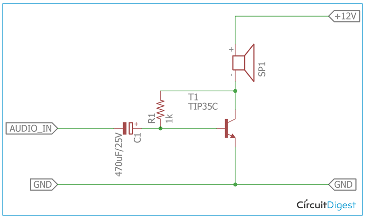
The circuit diagram for TIP35C Audio Power Amplifier is shown below.
Working of TIP35C Audio Power Amplifier
A transistor acts as an amplifier by amplifying the input signal. If a DC bias voltage is applied across the emitter-base junction of a transistor, the transistor remains in a forward-biased condition that can be maintained irrespective of the signal’s polarity. This is a Class A amplifier. Therefore the transistor always biased in ON state. Thus, during a complete cycle of the input signal, the transistor produces minimum distortion in the maximum amplitude of the output signal.
As a Class A amplifier requires to drive a high amount of load current the transistor rating must be adequate to compensate with the high collector current. The load, i.e the Loudspeaker is connected across the collector. Therefore, the transistor must have a high collector current. This is successfully delivered by the TIP35C as it is a 100V power transistor along with a 25A of collector current. However, the major disadvantage of the above circuit is the overall efficiency of the power amplifier. Since the circuit is a basic construction of class A amplifier, almost a large amount of current is lost as heat dissipation across the power transistor TIP35C. It is mandatory to connect a large heatsink to accommodate heat dissipation. The conversion efficiency of the circuit is low.
The in detail pin diagram of the TIP35C is stated in the below image
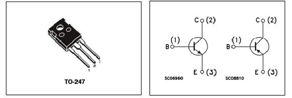
The resistor R1 is used as a base resistor which is providing sufficient base current to drive the transistor in saturation point. The 470uF capacitor C1 is an essential component of the circuit. This is because the capacitor is serving two purposes. First of all, the capacitor is isolating the base with the input supply source so that the base voltage or current could not affect the audio source, and the other purpose is to act as a DC blocking capacitor from the input source. Capacitor blocks DC and only passes AC. This is effectively served by the 470uF capacitor and it allows only AC frequency to pass.
Power supply positive is connected in series with the loudspeaker. The Transistor is sourcing the speaker with GND. Therefore, small changes in the base could manipulate the load, i.e loudspeaker.
Testing 12V Power Audio Amplifier
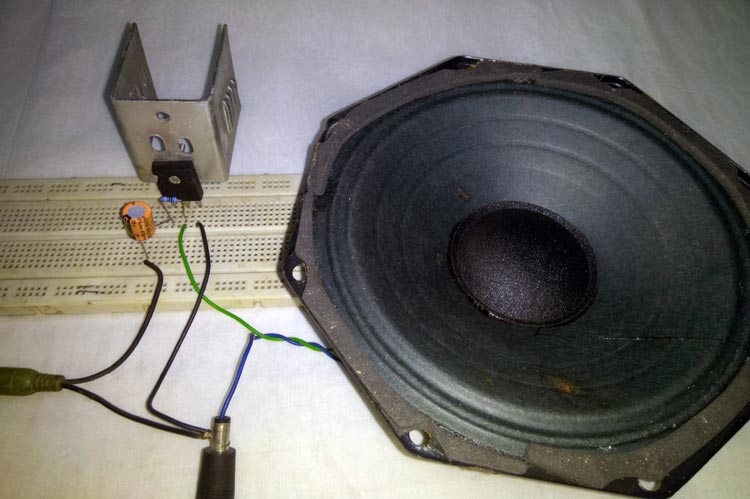
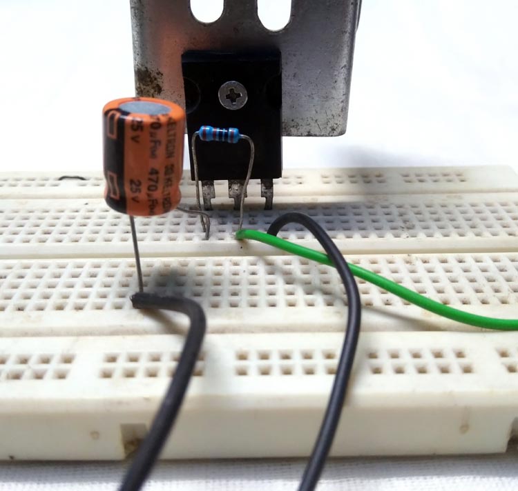
The circuit is constructed in a breadboard. My breadboard set-up looks something like this below. As you can see the circuit requires very less external components and hence easy to construct
The circuit is tested using a 9 Watt speaker which is shown in the below figure
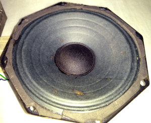
Selecting the right Speaker is important for any power amplifier. A poor performance speaker can ruin a well-constructed amplifier. So, for anyone who is constructing an audio-related application board where the speaker is the main road, be sure that you have a well functioning speaker. For the testing of this power amplifier circuit, the above speaker is used. This speaker is more than 60 years old and it is harvested from an old tube amplifier. However, this speaker is reconstructed by me almost three years ago. It is a 4 Ohms speaker that can provide almost 9 Watt of power output and the diameter of this speaker is 6 inches in diameter.
The next thing is the audio input. The audio input is given by a mobile phone. Since a mobile phone already has an inbuilt preamplifier, it can be considered that the testing is done with a basic preamplifier before the power amplifier during the testing phase. The circuit worked pretty well and the output performance is quite well. The full testing video can be found at the bottom of this page.
Conclusion
It is a basic type of Class A power amplifier circuit with 12V input and using a minimum component, only three. However, it is not as good as the traditional Power Amplifier available in the market. Further improvement can be done and the overall performance can be increased.
Further Improvements of the circuit
The circuit can be further improved by adding a complementary PNP power transistor and configuring the circuit as a push-pull power amplifier. In such a case, additional filter or transistor-based pre-amplifiers can be used to compensate with the amplitude voltage needed for the circuit. In addition, an equalizer circuit can also be added for proper BASS, MID and TREBLE performance.

