Different Electronic systems operate in different level of voltages. Most commonly the digital electronic systems like microcontrollers and microprocessors operate in 5V or 3.3V. Industrial Level Control devices like PLC, HMI etc. have an operating voltage of 12V, 24V etc. The loads (LED indicator) and sensors, that are used to interface with a PLC, also have a nominal operating voltage of 24V. Other than that few automobile wiring harnesses also operate on 12V or 24V. There are also 24V bulbs that are used in tail lights or head lights of automobiles. So in this tutorial we learn how we can flash two 24V bulbs using a simple circuit.
Real world observance
Before we get into the 24V flasher relay circuit diagram and working of the circuit, let us make a small practical observance. A bulb flasher circuit is a very common circuit which most of us would have come across in our day to day life. One very obvious example is the indicator lights on our automobiles. As soon as the indicator is singled the bulb inside the indicator begins to blink, this is done with the help of a flasher circuit. Now if you observe close you should also be able to hear a ticking sound every time the light turns on or off. This is due to the relay that is being switched to turn on or off the light. So the next time when you get your hands on the wheel of your car and turn on an indicator, pause for a second and enjoy the sound of the relay ticking inside your dashboard. So now we know that we need a relay to be ticking to turn on and off our led bulb. This ticking circuit will be designed using a 555 timer.
Materials Required
The following are the components required to build this circuit
- 24V Bulb (2 Nos)
- Relay 5V
- 555 Timer IC
- 7805 Regulator IC
- BC547 Transistor
- Diode 1N4007
- Resistor (1k, 470k)
- Capacitor (10uf,0.1 uf)
- 24V Power supply
- Breadboard and connecting wires
Circuit Diagram
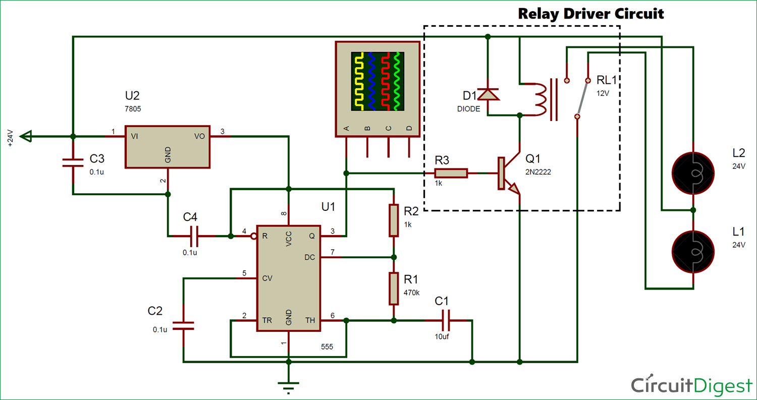
The complete circuit diagram for the 24v bulb flasher relay circuit is given below. It was built using proteus and the simulation of the same will be discussed further below in this page.
As we know the circuit involves a relay, and the two bulbs that we wish to flash is connected to the relay. The positive ends of the bulbs are tied together and connected to the 24V supply, in order to switch the bulbs the negative ends are connected to a relay. The common pin of the relay is connected to the Relay and the normally open (NO) pin is connected to one bulbs negative end and the normally closed (NC) pin of the relay is connected to the other bulbs negative end. This way only one bulb will be turned on at any given time.
Now this relay has to be turned on and off in a particular interval of time. In electronics whenever we are dealing with timing signals the first and basic choice would be to utilize a 555 Timer. Here also we will use a 555 timer in Astable mode to produce a pulse with a predefined on-time (Ton) and a off-time (Toff). In our circuit the Bulb 1 will be turned on only during the on-time and the bulb 2 will turned on only during the off-time. We will learn more about this operation in the simulation part.
The operating voltage for this circuit is 24V, but the 555 timer and Relay requires a lesser operating voltage. So we use a 7805 which is positive voltage regulator and it will regulate the 24V to 5V and we can use this voltage to power the 555 timer and Relay. The NPN transistor BC547 (or 2N2222) is used to turn on or off the relay using the 555 timer, because the source current from the 555 pin 3 will not be enough to turn on or off the relay so we use a transistor in between through a base resistor. This circuit is called a relay driver circuit, which is highlighted in the circuit diagram above. Learn more about relays here.
Simulation of Flasher Circuit
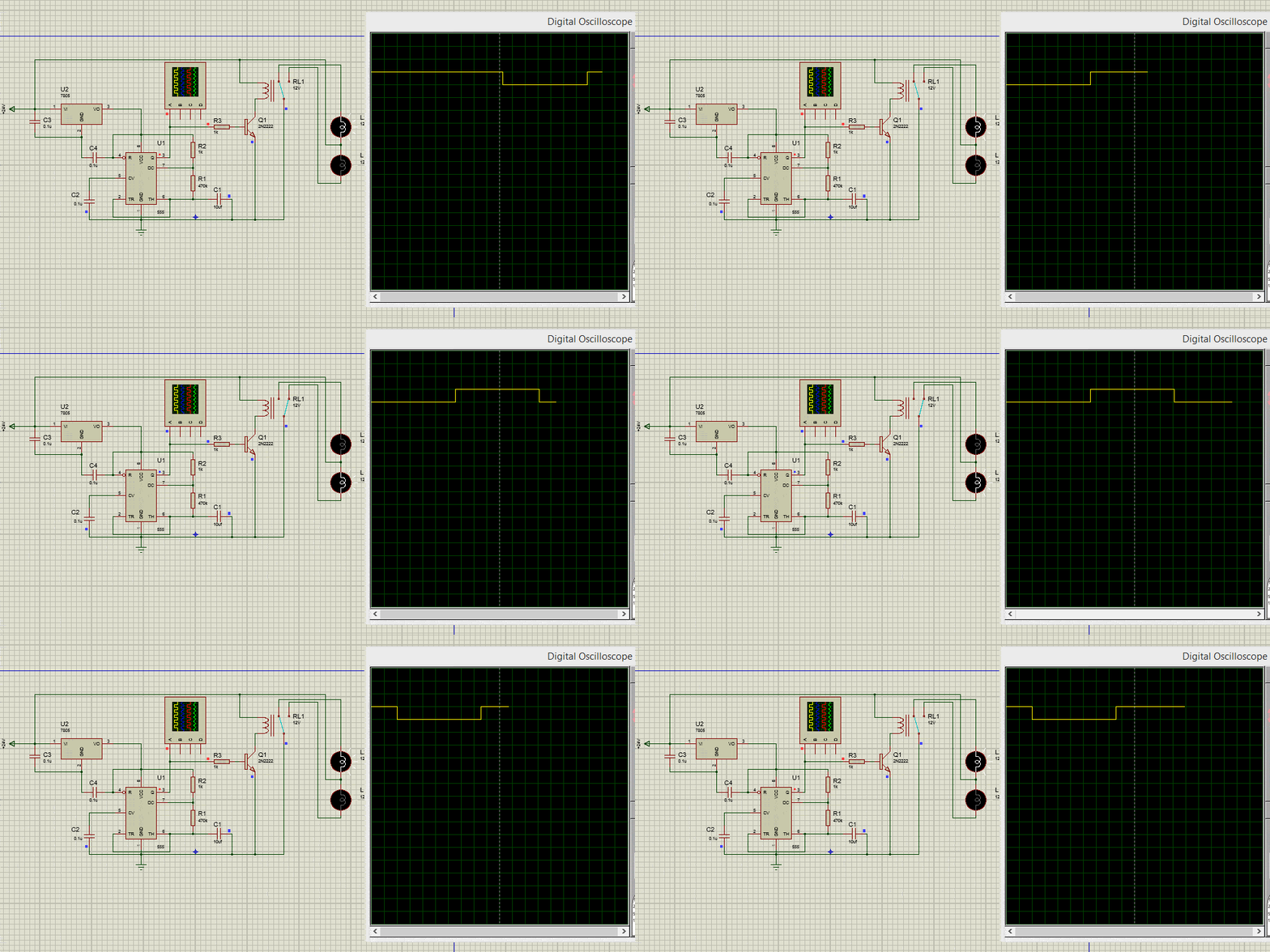
When the circuit is powered, the 555 Timer IC should provide a pulse with a predefined On time and Off time. This pulse will then be used to turn on/off the relay through a transistor. The relay will then decide which bulb should be turned on. The GIF file below shows the Blub being triggered and the pulse wave produced by the 555 Timer
The On time and Off time of the pulse decides how long each bulb stays in on state. We can set this time by selecting the appropriate value of resistor (R1 and R2) and capacitor (C1). If we take a look at the circuit diagram above we can notice that in this circuit we have set R1 and R2 value to be 470k and 1k respectively and the capacitor C1 to be 10uf.
The formulae to calculate the ON time (Ton) of the circuit is given below, let us substitute the value of R1, R2 and C1 in the circuit to calculate the time value.
TON = 0.693 (R2 + R1) C1
= 0.693 (470000+1000) 10×10-6
= 3.26 seconds
Similarly, the formulae to calculate the OFF time (Toff) of the circuit can also be calculated using the formulae below
TOFF = 0.693 (R2) C1
       = 0.693 (470000) (10×10-6)
       = 3.25 seconds
555 timer is configured in Astable mode here, so learn more about these values and 555 in Astable mode here.
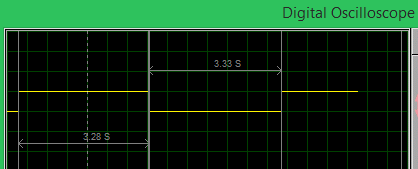
We can also verify the values using the digital oscilloscope in proteus simulation. A snap shot of the waveform is shown below. I have used the cursors option to measure the time duration of the on and off pulse. As you can see the ON time was measured to be 3.28 seconds and the OFF time was measured to be 3.3 seconds which is close to the calculated values. However remember that these are theoretical values and you cannot expect them to be exactly the same on practical circuit.
Working of Flasher Circuit
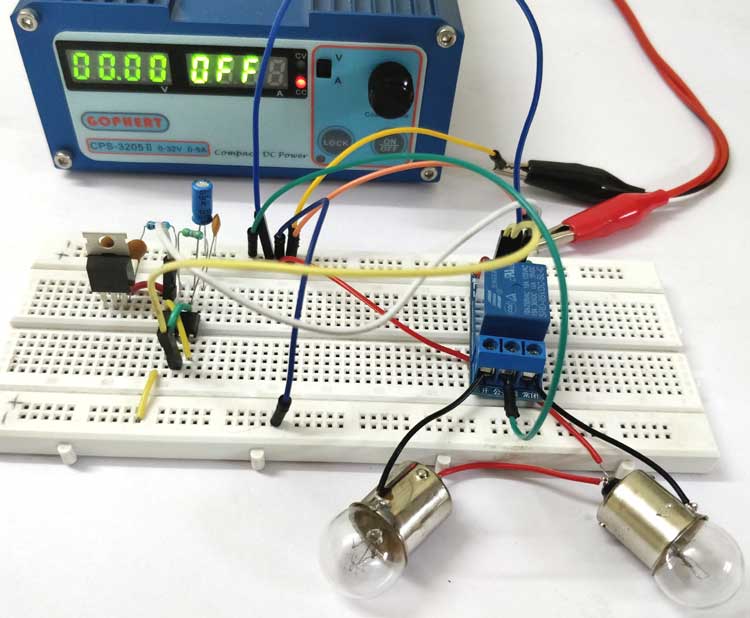
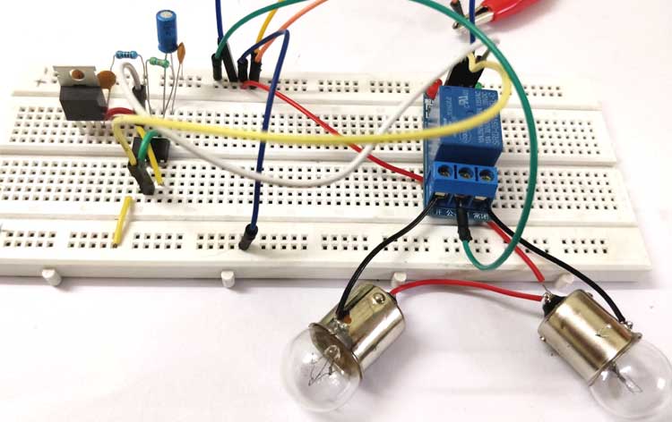
I have build the complete circuit on top of a breadboard, you can use a perf board to solder the components if you planning to use it for a long time. Once all the components were connected my experimental set-up looked something like this below.

I have used my RPS to act as a power source and it set to deliver 24V with a maximum current of 1.5A, since the bulbs that I have used here consume about 1A each at 24V. Also I have used a 5V relay module to make the circuit look neat. The relay module is nothing but a collection of the Relay, Diode and transistor, you can also use one if desired. Just power the relay module using the Vcc and ground pin and connect the signal pin of the module to pin 3 of the 555 timer. Connect the Common (C), Normally Open (NO) and the Normally Closed (NC) terminals of the relay to the bulb and ground line as shown in the circuit diagram.
Once the connections are done, simply turn on the power supply and you should notice the bulbs flashing one at a time. If you have any problem in getting it to work, use a multimeter to debug the circuit since you have already understood the working of the circuit (which I believe) it should be easy for you to debug the circuit by checking the voltage levels at the pins. If you still face problems use the comment section to get help or use the forums for more technical help.

