In this DIY project article, we will build a simple, cost-effective, powerful LED driver circuit that could be useful to power up an entire 12V light string that has more than 100 or even 200 LEDs. As there are many led driver projects that we have covered on our website, this is a very miniature version and can only be used for lighting a LED strip.
Note: It is requested not to use this power supply other than lighting up led strips as this does not include any kind of input protection as well as EMI filtration. This device is very dangerous to use as it uses a direct 230VAC power source to convert the 12V output in an isolated manner. It is only having output short circuit protection and nothing more than that.
Components required for AC to DC LED Strip Driver
|
Quantity |
Component |
Comment |
|
1 |
MB10S |
Bridge Rectifier |
|
2 |
4.7M Ohms |
0.25W |
|
1 |
TNY285DG |
AC/DC Converter |
|
1 |
22uF / 400V |
|
|
1 |
UF4007 |
Ultrafast Plastic Rectifier |
|
1 |
SMBJ160A |
TVS DIODE |
|
1 |
Transformer |
Self-Made or purchased, Description given |
|
1 |
PC817 |
Optocoupler |
|
1 |
1k |
0.125W |
|
1 |
210R |
0.125W |
|
1 |
SB380 |
Any 3A 80V schottky diode can be used |
|
1 |
22R |
0.25W |
|
1 |
470pF 200V |
Any package / SMD or TH |
|
1 |
TL431 |
|
|
1 |
100nF 50V |
Any package / SMD or TH |
|
1 |
43.2k |
0.125W |
|
1 |
11.3k |
0.125W |
|
1 |
Veroboard |
|
Transformer Construction
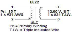
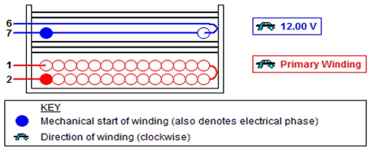
Most of the times transformers are not available off the shelf in the exact same parameter that suits our design. So, here we are going to design our own transformer as required by our circuit design. Below is the diagram of transformer construction -
Mechanical Diagram -
Materials Required for Transformer Construction
Here are the materials that are required for the transformer construction-
|
Item |
Description |
|
1 |
Core: EE22, 3F3, gapped for ALG of 346 nH/T² |
|
2 |
Bobbin: Generic, 5 pri. + 5 sec. |
|
3 |
Barrier Tape: Polyester film [1 mil (25 µm) base thickness], 8.45 mm wide |
|
4 |
Varnish |
|
5 |
Magnet Wire: 34 AWG (0.16 mm), Solderable Double Coated |
|
6 |
Triple Insulated Wire: 24 AWG (0.55 mm) |
To Construct the Transformer, kindly get the Bobbin and the above-mentioned materials. Please use the below steps –
- Start on pin 2 first and wind 85 turns.
- The wire should be 1 filar of item 5 which is the 34AWG copper wire, make sure it is Solderable Double-sided coated.
- Now slowly go to the 2nd layer from left to right. Winding direction is always clockwise.
- At the end of 1st layer, continue to wind the next layer from right to left.
- On the final layer, spread the winding evenly across entire bobbin. Finish this winding on pin 1. Add 3 layers of insulation Tape that is the 3rd Item of the list.
- Start the Secondary winding. Start on pin 7 and wind 8 turns single filar of item 6.
- Spread the winding evenly across the entire bobbin. Winding direction is always clockwise.
- Finish this winding on pin 6. Add two layers of tape.
- Assemble and secure the Core Halves.
- Dip Varnish the transformer uniformly and do not Vacuum impregnate.
For a more detailed explanation of Transformer construction kindly check the article on How to Design your own Transformer.
AC to DC LED Strip Driver Circuit Diagram
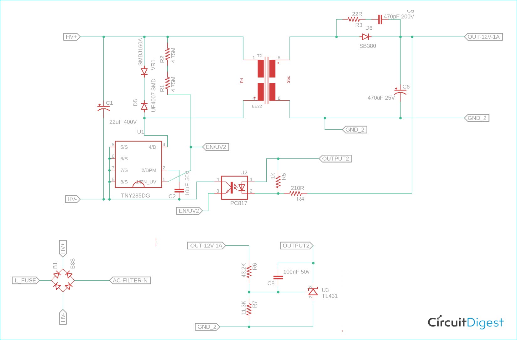
The complete circuit for building a 12V LED Strip Driver Circuit is given below:
Before describing the working of the LED Strip Driver, it is essential to know the working principle of the circuit. This circuit is highly dangerous and needs to be enclosed completely. However, for understanding purposes, it is done using bare Veroboard. But before that let's explore the circuit operations -
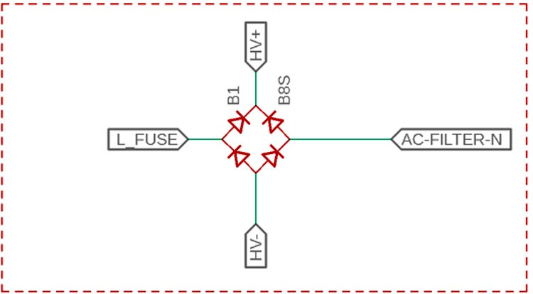
This is a bare diode bridge rectifier circuit to convert the AC input to DC.
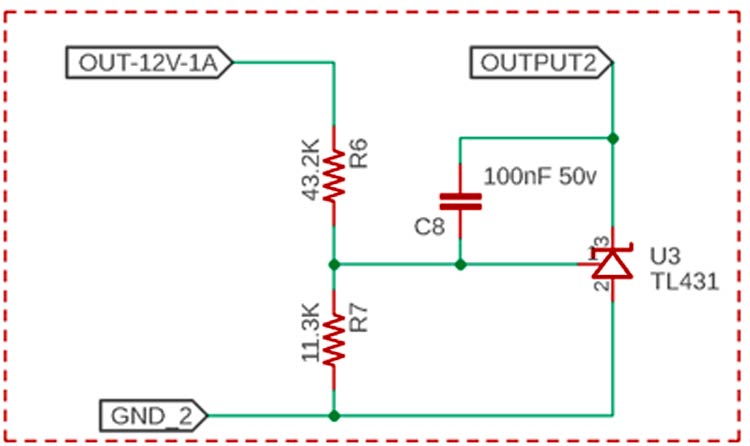
This is the Feedback section. The voltage is set using the R6 and R7. TL431 is a configurable Zener diode and it controls the feedback section.
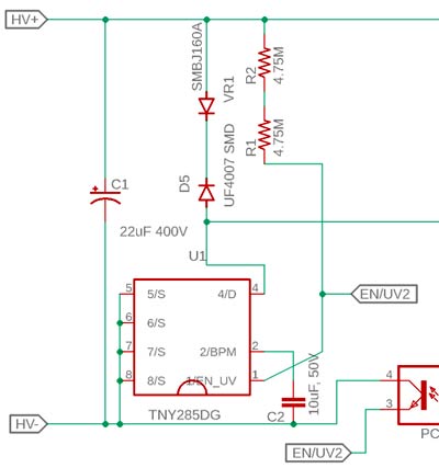
This is the primary section. The C1 capacitor is the feedback capacitor across the input. The TNY285DG is the main controller that is driving the Transformer. This works in a very high-frequency switch at 125kHz. The C2 is used for internal usage of the U1. R1 and R2 are the two resistors in series that are used to sense the under-voltage lockout where the U1 will skip the switching if the input voltage is less. The D5 and VR1 are used to protect the U1 from transients generated from the huge leakage inductance of the transformer. These two diodes are very essential.
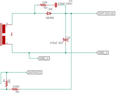
The SB380 is a 3A 80V Schottky diode and any same rated Schottky diode will work. The RC snubber R3 and C5 are used for protecting the diode from high transient changes. C6 is the output capacitor having 470uF 25V voltage. The PC817 is the optocoupler used for feedback sensing.
Testing the LED Driver Circuit
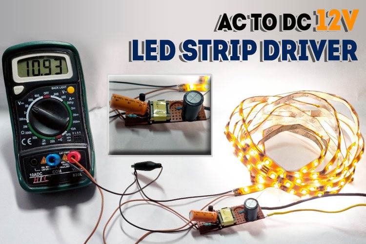
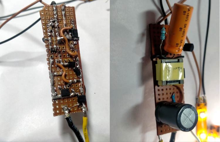
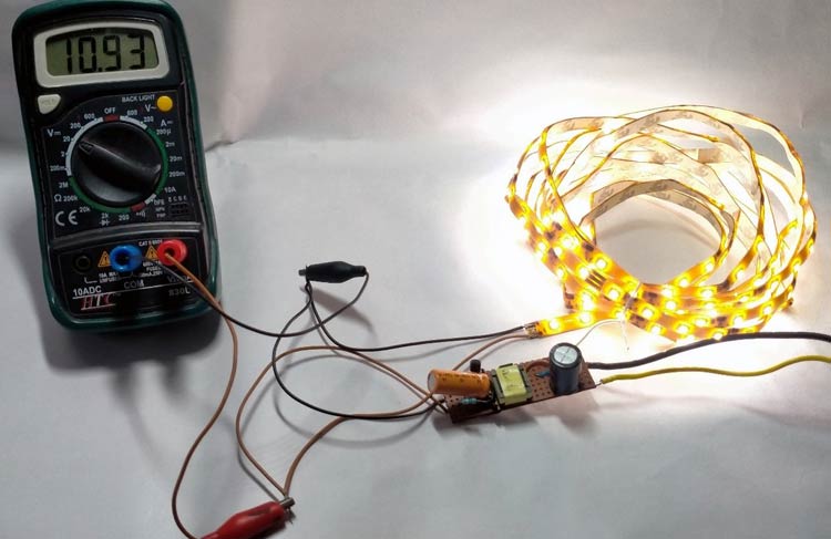
The circuit is soldered in dotted Veroboard. This is a high voltage project, so lots of wire isolations are done on the PCB. It is better to use a PCB to be on the safe side. Once everything was ready, I first measured the output voltage using a Multimeter and after confirming the output voltage I connected the LED strip as shown in the image below:
The working of the project is shown in the video below. Hope you understood the project and enjoyed learning it. If you have any doubts you can post them in the comment section or in our forum.

