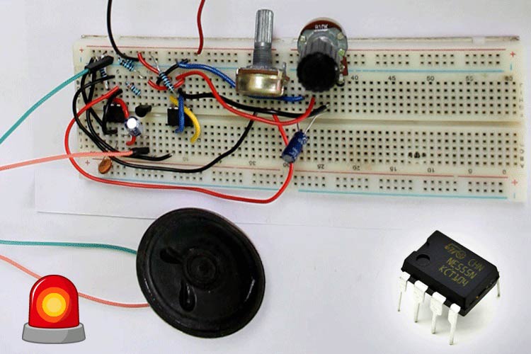
Upon hearing a siren of a nearby police vehicle, one might think about how this tone is being generated. You’ll be surprised to know that the brains behind these tones are not a microcontroller but a humble NE555 timer IC. If you know a little about electronics then you must have heard of 555-timer IC and its 3 very popular circuits the astable multivibrator, the bistable multivibrator, and the monostable multivibrator. We have discussed the working of all these three modes previously, you can check them out if interested.
In this project, we will use the astable mode of this IC with some external components to generate a police siren tone. For demonstration, I designed the circuit on the breadboard. Previously, we have also built a siren generator circuit using UM3561 IC but for this tutorial, we will be using the more commonly available 555 Timer Circuit.
Components Required for Designing 555-Timer based Police Siren
The list of components required for designing a police siren circuit is given below:
- Breadboard
- 555-timer IC*2
- Capacitors: 10uf, 0.01uf, 47uf, 100nf
- Resistors: 1k, 4.7k, 10k
- Potentiometer: 100k and 50k
- 9V battery
- Breadboard jumper wires
Introduction to the 555 Timer IC
When it comes to designing timer circuits, the very first thing which comes to mind is the 555 timer IC. It’s the oldest piece of tech and thus you can rely on it blindly and best of all, it’s affordable. The internal circuit of the 555-timer is discussed below:

PIN 1 and PIN 8: These are connected between the ground and Vcc with three 5kΩ resistors. This is from where this IC got its iconic name. These resistors create a voltage divider circuit with the value of 1/3 and 2/3 of the supply voltage as pin 1 is ground and pin 8 is Vcc. The non-inverting input(+) of one comparator is connected to the 1/3 output of the voltage divider and the inverting input(-) of the other comparator is connected to the 2/3 output of the voltage divider.
PIN 2: It is the trigger pin of the IC which is connected to the inverting input(-) of the comparator.
PIN 3: It is the output of the IC which is connected via the output driver circuit to the output of a flip-flop.
PIN 4: It is the reset pin that is connected to the reset pin of the flip-flop. By connecting this pin to the ground, we can reset this IC. This is the reason we see most 555 circuits are connected to Vcc.
PIN 5: It is the control pin that is connected to the 2/3 value of the voltage divider and inverting input(-) of the comparator. If we want to change the reference voltage, we can apply external voltage via this pin. Generally, in most of the 555 timer circuits, we can see that this pin is connected to a capacitor for getting a stable reference voltage.
PIN 6: It is connected to the non-inverting(+) input of the comparator circuit whose output is connected to the reset pin of the flip-flop.
PIN 7: It is the discharge pin that is connected to the collector of the BJT.
Circuit Diagram for Police Siren Circuit
The circuit diagram of the police hooter circuit is explained below:
We are using both 555-timer IC’s in astable mode. Like most 555 timer circuits, IC pins 2 and 6 are connected. Pins 1 and 8 are connected to ground and VCC respectively for both the ICs. A resistor of 1k and 10k is connected between pin 7 and VCC respectively. A potentiometer is connected between pin 7 and pin 2 for controlling the siren tone. Pin 3 of IC 1 is connected to pin 5 of IC 2 through a 4.7k resistor. At pin 3 of IC 2, a speaker is connected through a 47uf capacitor which is the final output of the circuit.
Working of Police Siren Circuit
Both the ICs are working in the astable mode which means they are generating a continuous sequence of pulses on their output. We know that pin 5 of the IC is the control pin and thus by connecting it to an input voltage, we can change the reference voltages of comparators and thus the final output of the IC. The output of the first IC is connected to pin 5 of the second IC which in result modulates the output of the second IC according to its output pulse. The output of this IC is connected to an 8-ohm speaker via a 47uf capacitor which creates a tone that resembles the sound exactly like a police siren.
Testing of 555 Timer Siren Circuit
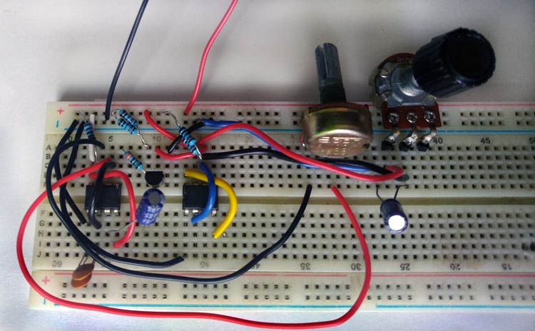
The image of the designed circuit is given below:

Note that you can also use a PNP transistor by connecting its emitter to pin 5 of IC 2 and collector to the ground. The switching of this transistor is depending on the first IC. We are doing this so that the control pin of the IC will get a stable voltage and thus give a stable reference voltage to the comparators. This will remove the fluctuations and the output siren tone will be much clear. Still, if your sound is not clear you can use a very small valued resistor (around 10-ohms) in series with the speaker.
This is all about the 555-timer based real police siren circuit. The video showing the working of the circuit is given at the end of the article. I hope you understood everything about the concept. Still if you have any doubt, feel free to ask in the comment section below.


