In electronics and electrical systems, faults are very common. The most commonly appearing fault is due to discontinued connection or open circuit. To rectify such kind of faults, one could go through all the lines to identify the fault itself. Though, this method fault search is generally replaced by continuity testing equipment. There are many ways of open circuit testing or fault identification. There are many circuits and designs for continuity testing. [Also check: Broken wire detector circuit]

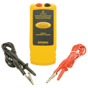
The above figure shows one of the continuity testers. The two probes connected to the ends of the line where fault is to be found.
In this project we are going to design a simple circuit that can be used for continuity testing. This circuit is developed from 555 IC timer circuit. It is a simple, cost effective and easy to design circuit.
Circuit Components
- +5 to +9 supply voltage
- 555 Timer IC
- 1KΩ (x2), 10KΩ and 100Ω resistors
- 104 (100 nF) capacitor
- Speaker (8Ω)
- 2N3906 PNP, 2N3904 NPN transistor
- Testing probes
Circuit Diagram and Working Explanation
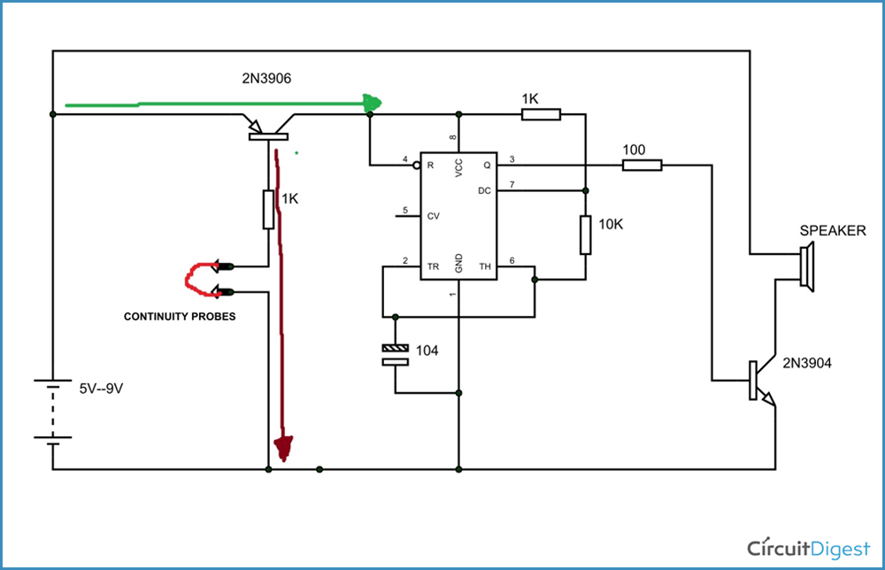
The above figure shows the circuit diagram of continuity tester. The 555 IC timer here is acted as an ASTABLE vibrator. The output of the timer is fed to the 2N3904 NPN transistor base to drive a speaker.
The capacitor here can be changed, however the selection of capacitance to be in the audible frequency range. If the selected capacitance is very low, the frequency output will be high and so we will not hear the sound. If the capacitance is high we get ticking sound and that is not good for testing. You can calculate the required output frequency with this 555 Astable calculator.
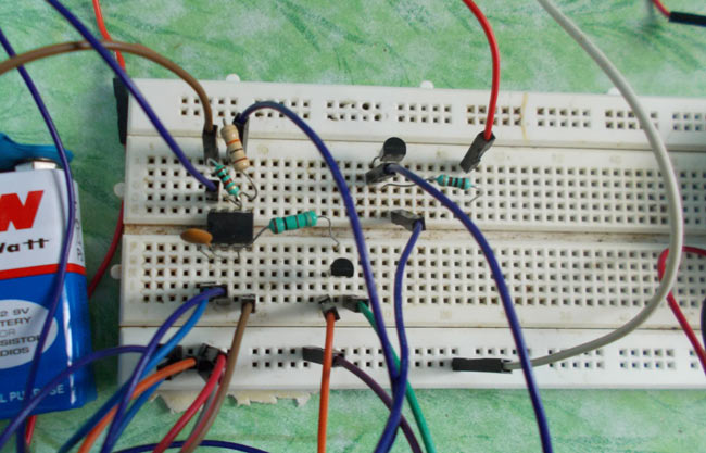
The circuit components are connected as shown in the continuity testing circuit diagram shown above. The power is turned on. Then the speaker will not make sound by turning on. Here the power driven to the timer flow through PNP transistor. Since, base of the transistor is open circuited, as shown in figure, the current does not flow in to the timer chip. So there will be no square wave and so there will be no pulse at the base of NPN transistor. So there will be no sound.
One must remember that to turn on the PNP transistor, base should be connected to ground.
Here is the trick for continuity tester. The base on the PNP (which delivers power to timer on grounding base) and a terminal from the ground from a pair. This pair is used for continuity testing. When these two terminals are connected together or flow through a short circuit, the PNP turns on and delivers power to timer and timer gives pulses to NPN (2N3904) to drive speaker. So when these two terminal are shorted are driven through some resistance we get noise. This noise will verify that there is continuity in the line.
As shown in above figure, when the base of PNP and the ground are connected to a non-open circuited line, the base gets a ground connection at the base so the current flows (brown arrow) from base of PNP to ground, tuning the transistor ON.
With the transistor ON, the current flows through the transistor to the timer chip. By this power the timer puts out pulses needed to generate sound. When the pair is connected across a open circuited line the PNP will be off and so no power to timer, there will be no sound indicating that it’s an open circuit line.
This is how this circuit can be used for continuity test.


