Switching Mode Power Supply or simply SMPS is a type of Power Supply Unit (PSU) that uses a switching device (such as transistor or MOSFET) to convert the source that can be AC or DC to a constant DC voltage. Switched-mode power supply circuits (SMPS) are most often required in many electronic designs to convert the AC mains voltage to a suitable level of DC voltage for the device to operate. This type of AC-DC converter takes in the 230V/110V AC mains voltage as input and converts it to low-level DC voltage with the help of the switching process, hence the name switch mode power supply. We have already built a few SMPS circuits earlier like 5V 2A SMPS circuit and 12V 1A TNY268 SMPS circuit. We even did a project on how to build our own SMPS transformer that could be used in our SMPS designs along with the driver IC. In this project, we will build another 12V 2.2A SMPS circuit using the UC3843 Current Mode PWM Controller IC, which is a popular low-cost SMPS driver IC. This tutorial will take you through the complete circuit and will also explain how to build your transformer for the UC3843 circuit. Interesting right, let's get started.
UC3843 Based Power Supply Design Specification
The UC3843 is a fixed frequency-mode PWM controller, it is specially designed for Off-Line and DC to DC converter applications with minimum external components. These integrated circuits feature a trimmed oscillator for precise duty cycle control, a temperature compensated reference, a high gain error amplifier, a current sensing comparator, and a high current totem pole output for driving a Power MOSFET. As we will see, it makes it suitable for many different applications.
Input specification: Our SMPS will work on AC to DC conversion domain. So, the input is AC. In this project, the input voltage is fixed. It is as per the European standard voltage rating. So, the input AC voltage of this SMPS will be 220-240VAC. It is also the standard voltage rating of India.
Output specification: We will set the output voltage to 12V with a 2.2A of the current rating. Thus, it will be 27W output. This SMPS will provide constant voltage irrespective of the load current, it will work in CV (Constant Voltage) mode. Also, the output voltage will be fixed at 12V rated.
Protection circuits: There are various protection circuits that can be used to design an SMPS circuit, to make the operation safe and reliable. The protection circuit protects the SMPS as well as the associated load. Depending on the type, the protection circuit can be connected across input or output. For this SMPS, input surge protection will be used with a maximum operating input voltage of 275VAC. Also, to deal with EMI issues, a common mode filter will be used for blanking out the generated EMI. On the Output side, we will include short circuit protection, over-voltage protection, and over-current protection. Other than that, to reduce EMI and noise we can use spark gaps or we can use
UC3843 IC Working
As we have discussed earlier, we will be using the popular UC3843 IC to design our SMPS, but before we do that, we need to understand the basic working of the IC. In this section, we will clarify some aspects of it. If you want to learn more, you can check out the datasheet of the UC3843 IC.
Under-voltage lockout: When the input voltage of the power supply drops below the rated/configured voltage the UVLO detection voltage kicks in, the UVLO sets the internal circuit to a semi-standby state to prevent any manufacturer of the circuit. When the power supply voltage rises and becomes higher than the UVLO release voltage, and the normal operation continues During Under-Voltage Lock-Out, the output driver is biased to a high impedance state. Pin 6 should be shunted to the ground with a bleeder resistor to prevent activating the power switch with output leakage current.
Error Amp Configuration: There are two error amps in this circuit. These two can be configured to sense voltage and current, to configure the current you can use the formula.
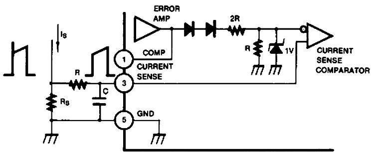
Peak current (IS) is determined by the formula.

A small RC filter may be required to suppress switch transients.
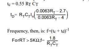
Oscillator Waveforms and Maximum Duty Cycle: Oscillator timing capacitor, CT, is charged by VREF through RT and discharged by an internal current source. During the discharge time, the internal clock signal blanks the output to the low state. The selection of RT and CT, therefore, determines both oscillator frequency and maximum duty cycle. Charge and discharge times are determined by the formulas:
Now, we know the UC3843 IC a little better so we can move to design the SMPS with it.
Components Required to build the UC3843 Based 27 Watt SMPS Circuit
The components required to build the UC3843 Based 27 Watt SMPS Circuit is listed below. We designed this circuit with very generic components, which makes the replication process very easy.
- Power Connector -1
- 1A TR5-370 Fuse -1
- MOV 275V -1
- 1N4007 Diode -4
- 100uF/450V Capacitor -2
- Common Mode Choke -1
- 18K,2W -2
- FR107 Diode -2
- 10K Resistor -4
- 22pF/100pF Capacitor -10 or 2
- 150K Resistor - 1
- 104 pF -1
- 4.7K Resistor -2
- 224 pF -1
- 100uF, 25V - 2
- 223pF -2
- 22R -1
- 1K Resistor -1
- 0.5R, 3W Resistor -1
- SR360 Diode - 2
- 3.3uF Inductor - 2
- 100uF Capacitor -2
- EL-35 Core and Bobbin - 1 (Salvaged From an ATX Power Supply)
Design and Construction of UC3843 Based 27 Watt SMPS Circuit
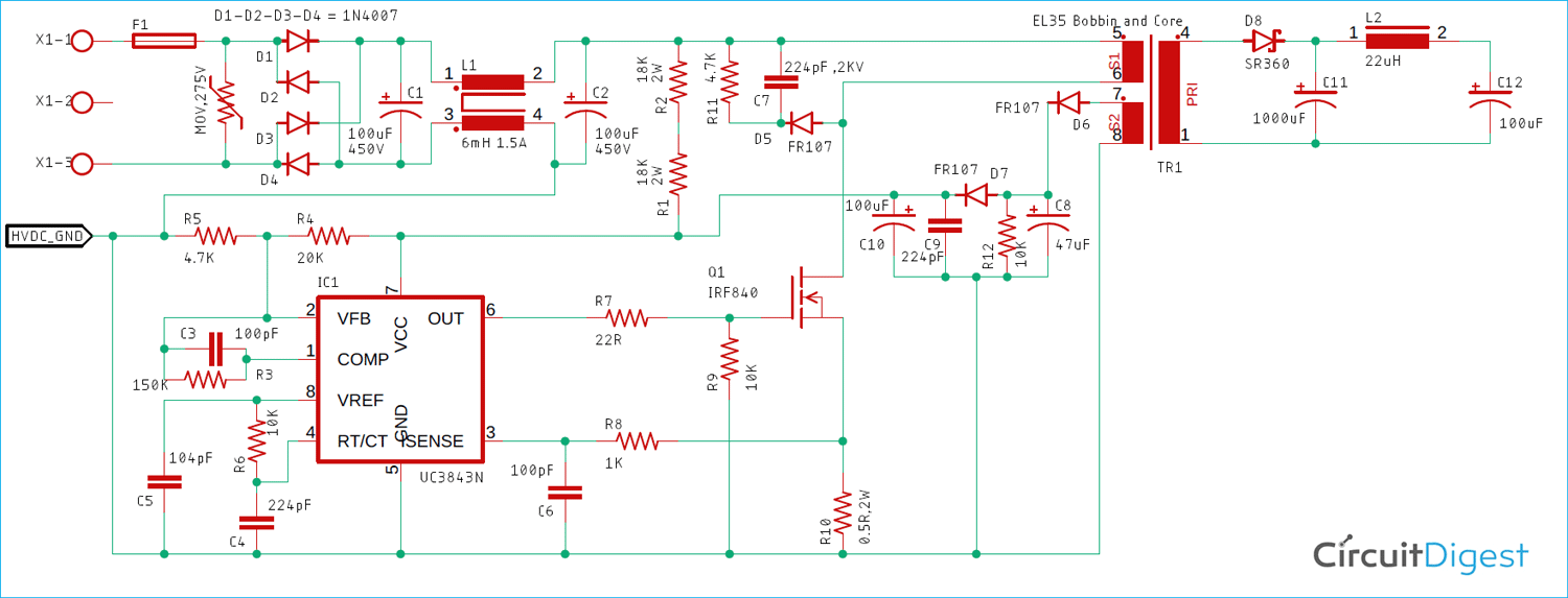
The schematic shown below is designed using the application note from semiconductor and I tweaked some components values according to my need because I already had those in my stockpile.
Before we build the circuit, it's better to understand the circuit operation, in this section, we will do just that.
Input surge and SMPS fault protection:
This section consists of two components, F1 and MOV. F1 is a 1A 250VAC slow blow fuse and MOV is a 7mm 275V MOV (Metal Oxide Varistor). During a high voltage surge (more than 275VAC), the MOV becomes dead short and blows the input Fuse. However, due to the slow blow feature, the fuse withstands inrush current through the SMPS.
AC-DC Conversion:
The AC DC conversion is done using four 1N4007 Diodes that make up a full bridge rectifier, a 1N4007is a 1000V 1A rated rectifier diode. The filtering is done using the 100uF 400V capacitor. However, for such a 25W circuit a 22uF 400V is sufficient.
PI Filter:
Different states have different EMI rejection standards. This design confirms EN61000-Class 3 standard and the PI filter is designed in such a way as to reduce the common-mode EMI rejection. This section is created using C1, C2, and L1. C1 and C2 are 10uF, 400V
Driver Circuitry or Switching Circuit:
For this design, the UC3843 alongside the IRF840 MOSFET forms the driver circuit to at initial startup some power is needed to start the operation, and the two resistors R1 and R2 comes in those are called the Startup Resistors these startup resistors provide the initial startup current to startup the circuit, and when the circuit is switching and it's on the auxiliary winding provides the power required.
Clamp Circuit :
The transformer is an inductor across the power driver MOSFET. Therefore, when the transformer turns off it creates a huge voltage spike. If not compensated correctly it could easily kill the MOSFET that is why a clamp circuit becomes necessary. Thus, the C7, R11, and D5 make up the clamp circuit.
Auxiliary Winding:
The Auxiliary winding provides power to the IC While it is in full operating condition. The power from the auxiliary winding is converted and filtered to DC using D6, D7, C8, C9, C10, and R12.
Secondary Rectifier and Snubber Circuit:
We need to convert the output of the TRansformer to DC before we can connect our applications circuits. An SR360 Schottky rectifier diode is used as the output current is 2A, SR360 is a 3A 60V rated Schottky diode.
Filter Section:
C6 is the filter capacitor. It is a low ESR capacitor for better ripple rejection. Also, an LC post-filter is used where L2 and C7 provide better ripple rejection across the output.
Oscillator Frequency Selection:
The frequency of the UC3843 IC can be adjusted according to needs, for our case, the Frequency of the IC is set to 80KHz with the help of the R6 Resistor and C4 capacitor. And an additional C5 capacitor is used to filter the power.
Construction of Switching Transformer for UC3843 Based 27 Watt SMPS Circuit
Let's now build the Switching Transformer, to do so we will use the information provided in the UC3843 Application Note.
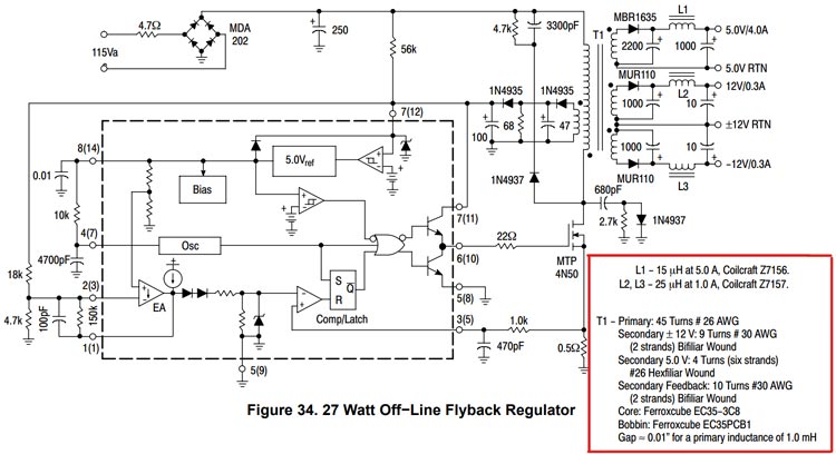
The Core is based on an EL35 bobbin and core with an air gap of 0.5mm. The primary inductance is 1mH. To build this transformer the following materials are needed.
- Polyester Tape
- EL35 Core pairs with 0.5mm air gap.
- 26 AWG copper wire
- 30 AWG copper wire
- Horizontal Bobbin (Salvaged from ATX Power Supply)
- Inductance Meter
Step1: Hold core in one hand and start with the 26AWG wire with pin 1, make 45 turns in a clockwise direction around the bobbin and finish it off at pin7, finally apply a layer of tape.
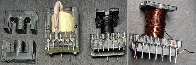
Step2: Start the bias winding using 30AWG wire from pin3 and make 10 turns in a clockwise direction and finish it on pin 5. Once done, apply three layers of polyester tap.
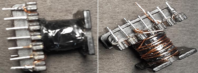
Step3: Start the secondary winding on the opposite side of the bobbin from pin1 and make 9 clockwise turns, and finish it off on pin3. And apply 3 layers of tape.
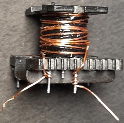
Step4: Secure the transformer with superglue/ duct tape to reduce vibrations and noise in the transformer.
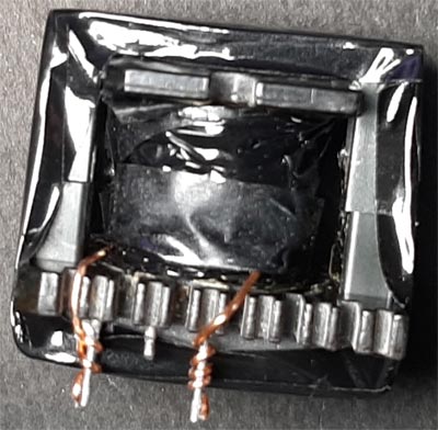
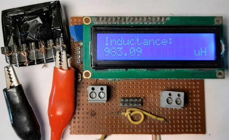
Step5: Once that is done measure the primary inductance of the transformer and if it's close to 1mH, you are done building the transformer at this point.
Building the UC3843 Based 27 Watt SMPS Circuit
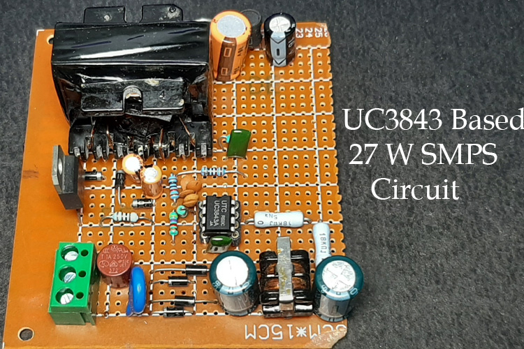
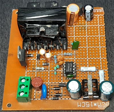
With the Switching Transformer, we constructed the circuit in a perf board and according to the given circuit diagram. Once all the soldering process was finished the board looks like the image shown below.
UC3843 Based SMPS Circuit Testing
To test the circuit, we connect the input to supply AC and we connect the output to the multimeter as you can see, we have 243V as input and 12.43V as output.
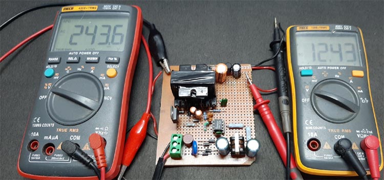
The output voltage is a little bit more than 12V due to tolerances, but when a load is attached the voltage is stable and working. The complete testing process is shown at the bottom of the page. Hope you understood the article and learned something new. If you have any questions, leave them in the comment section below.

