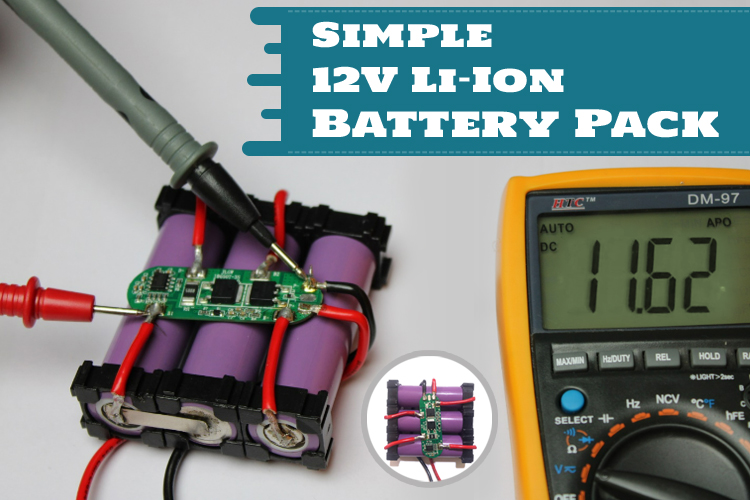
In this article, we will see how to design a simple 12V Li-Ion battery pack and how to use it with a protection circuit. A lithum-Ion battery is one of the most commonly used energy storage devices employed for powering equipment and gadgets in today’s time. Due to a high energy density and rechargeable capabilities, Li-ion cells are connected in different series and parallel arrangements to make a battery pack of different voltage output and capacities. Designing a simple battery pack and connecting it with a cost-effective protection circuit to make a robust battery pack that can be used to power RC cars, quadcopters, or other different gadgets running at 12VDC.
If you are interested to learn more about Li-ion cells you must be interested in the articles we have previously covered about different Li-Ion battery chemistries and you might also like to learn and design a 2S battery charger circuit we previously made.
Connecting Li-Ion Cells in Series and Parallel
Most Lithium cell chemistries have a Nominal voltage lower than 4 Volts. So, in order to make it usable for higher voltage applications, we might have to use a boost converter or we can design a battery pack that provides the required output voltage by arranging the cells in a combination of series and parallel connections.
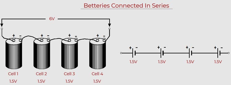
Connecting cells in Series: When the positive terminal of one battery is connected with the negative terminal of the second battery, the battery is considered to be connected in a series connection. In the case of a series connection, the total voltage of the battery is increased and is given by the sum of the voltage of all the batteries connected in series. The image below shows how a series connection looks like.
Connecting cells in Parallel: When the positive terminal of the first battery is connected to the positive terminal of the second battery and similarly the negative terminal of the 2 cells are connected together, the battery is said to be connected in a parallel connection. In the case of a parallel connection, the total capacity of the battery is increased while the voltage remains the same. The image below shows how cells in a parallel connection look like.

Making a 12 V battery pack
To make a battery pack, the first step is to know the nominal voltage of a cell. The cells selected by us have a nominal voltage of 3.7Volts while the charge voltage is 4.2V. So, in order to make a 12 V pack, we require 3 cells connected in series. The image of cells we used is shown below

We are selecting a 3.7V battery with a capacity of 1200mAh. So, with 3 similar cells of 3.7V 1200mAh and connect them in series as shown in the diagram below.
Note: Make sure to connect all the cells of the same capacity, else your battery pack’s life will be affected.
I took a 3-cell support bracket (or cell spacer) and placed 3 cells in such a way that the 1st and 3rd cell have their positive side facing down and the middle cell’s positive side facing up. After placing the cell, place another 3-cell support bracket and make sure the pack is secured and the batteries are fixed at their position. Now the next step is to connect the battery with each other in series. Let's call the 3 cells C1, C2, and C3. First, connect the +ve terminal of C1 with the negative terminal of C2 using a nickel strip and positive terminal of C2 with the negative terminal of C3 as shown in the image below.
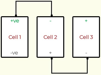
The next step is to connect wires from the negative terminal of C1 and another wire from the positive terminal of C3. The above configuration is called a 3S configuration or 3-series configuration and when the voltage between the positive terminal of C3 and the negative terminal of C1 is measured it will be equal to a 12V cell.
How to connect nickel strip to a battery
The best method is to use a spot welder. First, clean the surface of the cell and that of the nickel strip with a clean cloth to remove any dust or dirt particles from the surface. Place a nickel strip on the terminal of the battery and bring the prongs of the spot welder and make brief contact, you can repeat the process by rotating the battery to make an extra connection your battery is now securely connected to the nickel strip. Repeat the same step for making other connections.
What if you don’t have a spot welder?
The first step is to use a nail or any metal object and scratch all the terminals of the batteries you want to connect.
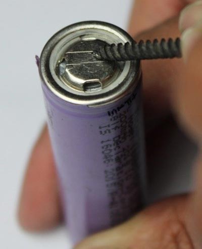
After scratching, put a small quantity of flux on the cell terminal and affix a little bit of solder on the terminal. Do the same for the nickel strip and connect the Nickle strip with the terminal of the cell.
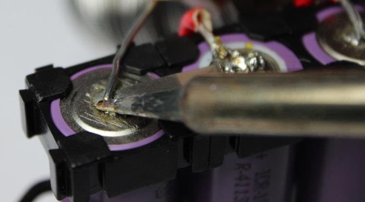
Repeat the step multiple times to make connections as required. Your 12V cell is ready.
Connecting a Battery Protection Module
Li-ion batteries require a battery protection module to keep the battery’s health fine. These devices protect the battery pack from getting damaged by over-charge, deep discharge, and even from over-current. It is essential for keeping the battery safe and extending its life. To keep our battery safe, we have used an over-a-shelf 3-S 6Amps Battery Protection Module or BMS Module.
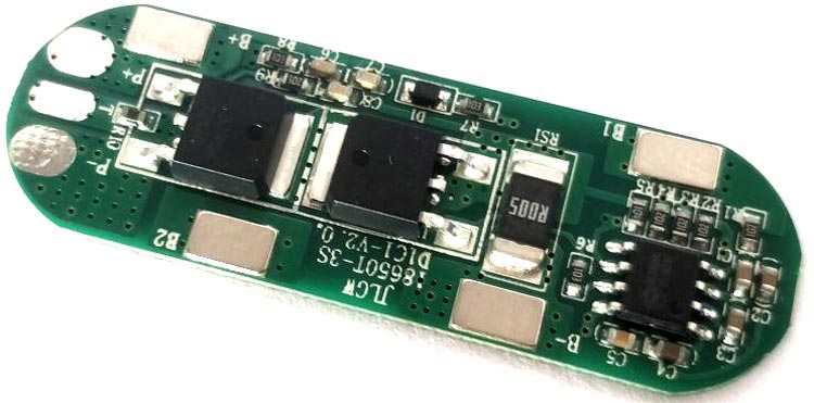
Connect a BMS module with the battery pack. Most BMS will have the same connection terminology.
P- Negative Terminal Connection for the battery pack
P+ Positive Terminal Connection for the battery pack
T For attaching the temperature sensor
B+ Positive terminal of the first battery
B- Negative terminal of the last battery
B1 Connection to 1st battery
B2 Connect with the 2nd battery
For measuring the temperature, you can use NTC thermistor. You will have to connect one end of the thermistor with the P+ terminal and the other end of the NTC thermistor has to be connected to the T pad on the BMS module.
Testing
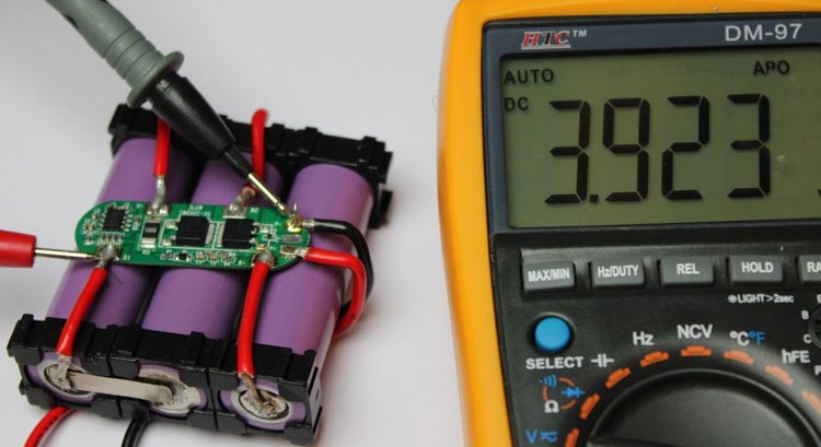
For testing the Module, after visually inspecting all the connections, check the voltage across P+ and P-. the voltage should be equal to the voltage across the B+ and B- pad. The next step is to test voltage across P- and B1, the voltage should lie be somewhere near 3.7V, since it is the voltage of a single cell.
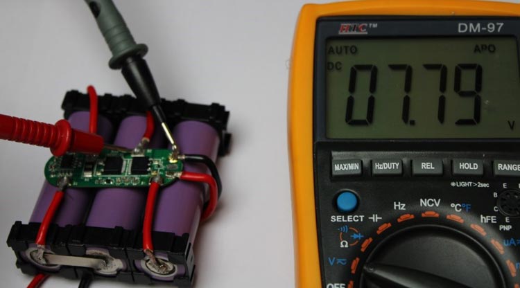
The next step is to test voltage across P- and B2, this measurement will give us the voltage between 2 cells connected in series, and the displayed voltage will be somewhere around 7.4V.
After testing all the pads, I used a 12 V charger to charge the battery pack and after half an hour, measured the voltage of the battery pack. The starting voltage of the pack was and the final voltage of the pack is given below:
|
Time |
Voltage |
|
Start |
11.58 V |
|
30 minutes |
12.03 V |
I also used the battery pack to power a bulb, motor, and other appliance, and the battery pack worked perfectly.
Conclusion
Knowledge of designing a battery pack is very essential as cells are seldom used as a single entity due to their low capacity and voltage, hence, cells are bunched together to form a battery pack. The voltage of the battery increases when cells are connected in series while the capacity of the battery is increased when the cells are connected in parallel. Due to the risk of damage to the Li-ion cells, battery packs are clubbed with a battery management system which ensures the proper working of a battery pack. BMS usually monitors, battery’s health, charge, voltage, and current while more advanced BMS can also monitor temperature and have the functionality to communicate the battery’s data to a remote location. I hope that you learned something new, if you have any doubts or questions regarding designing of the battery pack, then please feel free to write in the comment section below.

