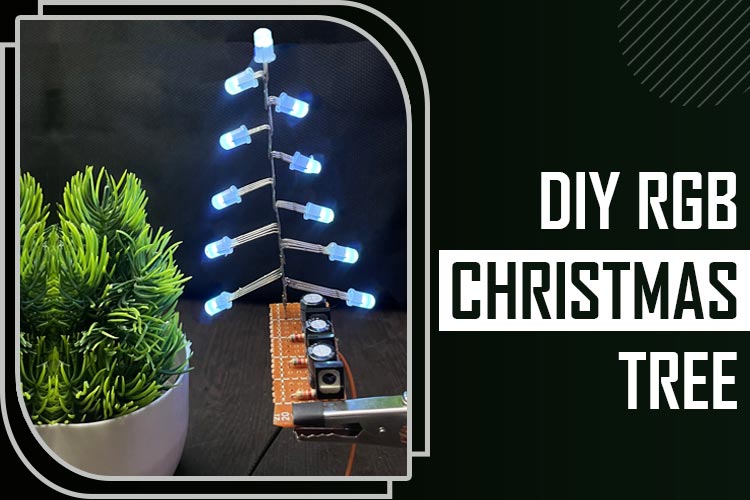
In this short tutorial, we will show you how you can build yourself a transistor-driven color-changing RGB LED lights. The building process is simple and requires only a few transistors, capacitors and resistors to build it. The lighting system built in this way is not only efficient but cost effective but it can also create stunning color effects that can transform any room.
RGB LED Pinout
The pinout of the common anode and common cathode RGB LEDs are shown below.
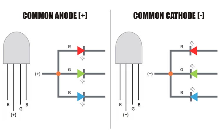
There are two types of LEDs common anode and common cathode and for this project, we will be using common anode LEDs. The common Anode LEDs have RGB in common and
Pin R The negative terminal of the common Anode LED or the positive terminal of the common cathode LED depending upon the common Anode or common Cathode configuration. Connecting it to Ground or VCC will light up the LED Red.
Pin G Connect the G pin to Ground in case of common Anode LED. Connect the G Pin to VCC in case of a common cathode LED. doing so will light the LED Green.
Pin B In case of a common Anode LED connecting the B pin to Ground will light up the LED. and if the LED is a common cathode, connecting it to VCC will light up the LED.
+/- Pin The (+) and (-) pins represent the common cathode or common Anode Pins of the LED. For a common anode LED connect this pin to VCC, for common cathode LED it should be connected to the ground.
Components Required to Build LED Tree
Components required to build the RGB LED Tree are simple and can be found in your local hobby store
- Common Anode RGB LED - 10
- 470uF Capacitor - 3
- 82K Resistor - 3
- BD140 Transistor - 3
- Perf Board
- Soldering Wire
- Jumper Wires
Circuit Diagram - Color Changing RGB LED Tree
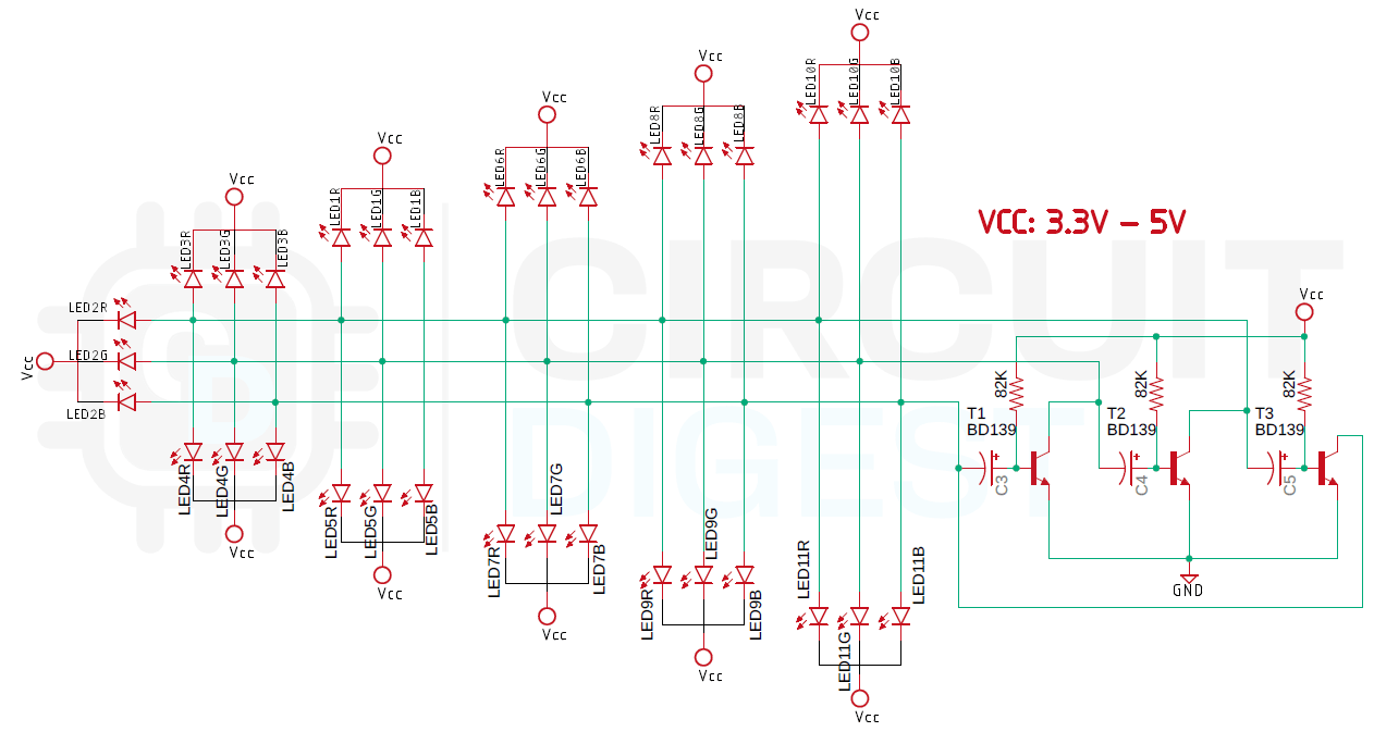
The complete schematic diagram of the color changing RGB LED Tree is shown below the circuit is very simple and easy to understand. The LEDs that we have used in the circuit are all common Anode LEDs, and all of them are connected in parallel. The working of the driver circuit is also very simple,
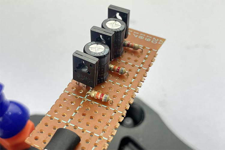
when power is applied to the circuit the capacitor at the base of the transistor starts charging, and after a certain period of time it will reach a threshold where the transistor will completely turn on and the LEDs corresponding to that channel will light up,
Now as current flows through the first transistor the capacitor to the next transistor starts charging and after a certain period of time the next transistor turns on and the LEDs corresponding to that transistor turns ON and the process repeats for the next set of LEDs. This is how the R, G, and B LEDs change colors.
Projects using RGB LEDs
We have built many other different projects, so
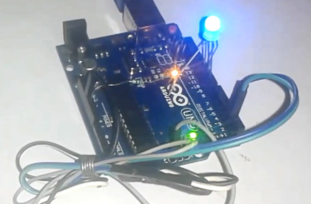
If you want to control some RGB LED lights with ESP8266 and Wi-Fi then this project is for you because in this project we have made a simple circuit to do so.
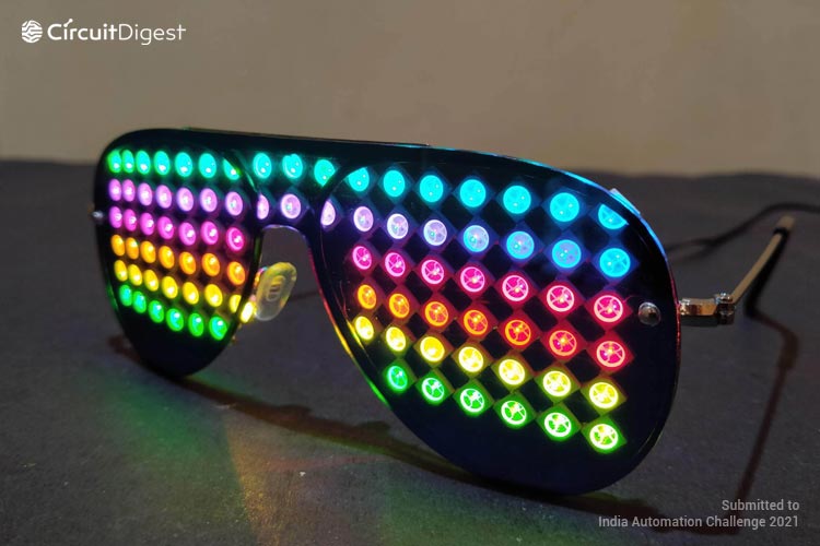
If you are looking for some cool, interesting and funkey project online which will make you stand out in a party then this project is for you, because in this project we have built DIY RGB LED glasses which can also display visual effects.
If you love spectrum analyzers like me then this project is for you because in this project we have made a DIY! Music spectrum analyzer with ARM microcontroller and Keil IDE.
Looking for a cool little night lamp on the internet, then this project is for you, because in this project we have made a cool little Android operated night lamp with Blunk app and ESP8266 microcontroller.

