Whether it’s your Laptop, TV, Smartphone, or any other electronic device, they all operates at different voltages. These devices have sensitive components like Microprocessors, ICs, etc. that works on very low voltage, and even the slightest change in voltage can damage these components. These sensitive components require a steady and stable voltage to operate optimally. So to provide a regulated output supply and protect the circuitry from voltage fluctuation, Voltage Regulators are used.
A voltage regulator is a cost-effective device to get a regulated output voltage from a higher or unstable input voltage source. It takes variable input voltage and provides a steady, low-noise DC output voltage. Voltage regulator comes in fixed and adjustable variants. Adjustable voltage regulator output voltage can be changed using the ADJ pin within its range. Here we have explained different types of Voltage Regulator Circuits and build one using LM317 Voltage regulator.
In this project, we will use MIC29302 to build LDO regulator or Low Dropout Regulator Circuit. The output voltage can be changed using high or low-value resistors at the adjusting pin.
Components Required
- MIC29302 Voltage Regulator
- Resistor (1KΩ)
- Potentiometer (10 K)
- Capacitor (10 µf and 0.1µf)
- Power Source (12V)
Circuit Diagram
This Low Dropout Regulator Circuit only requires few components. In this circuit, we are only using two resistors and two capacitors. The capacitor C1 is connected to the Vin pin of MIC29302 voltage regulator IC and used for the filtering of DC input voltage. Two external resistors R1 and RV1 are connected to the adjust pin and Vout pin of the IC. Resistors R1 and RV1 decide the output voltage Vout of the regulator. 10uF capacitor at output is used for stability and minimum output noise.
MIC29302 Voltage Regulator IC
MIC29302 is an adjustable five-pin voltage regulator IC, with a high output current of 3A and a voltage drop of 450mV at full load. MIC29302 regulator comes with TTL logic Enable pin to shut down the regulator when not in use; this makes it suitable for battery-powered equipment and linear voltage supplies. The MIC29302 has an Adjust pin by which output voltage can be set between 1.24V to 15 V using two external resistors.
MIC29302 is fully protected against reverse input polarity, overcurrent faults, reversed lead insertion and over-temperature operation. Its operating and storage temperature is in range of -40 to 125 °C and available in TO-263 and TO-252 packages.
MIC29302 have an output voltage range of 1.24V to 15V DC, and input voltage range is 3v to 16v. You can adjust the output voltage according to your requirement by using two external resistors connected through the ADJ pin of regulator. We can calculate the output voltage according to the below formula:
Vout = 1.25 (R1/R2 + 1)
For example, we are giving 12V as input and want 5V as output, so if R1 is 1kΩ then R2 can be calculated using:
R1/R2 =    {(Vout / 1.25) – 1}
1000/ R2 = {(5 / 1.25) – 1}
R2 = 1000/3
R2 = 333.33
So for 5v output voltage we need 333 Ω resistor at R2.
Pin Configuration

| Pin Number | Pin Name | Description |
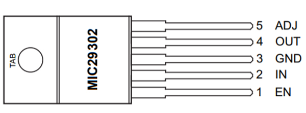
| 1 | Enable | TTL logic pin to turn on/off the regulator |
| 2 | In | Input voltage that is to be regulated |
| 3 | Ground | Connected to system ground |
| 4 | out | Regulated Output Voltage |
| 5 | Adjust | Sets the output voltage using two resistor divider network |
Working of Low Dropout Voltage Regulator
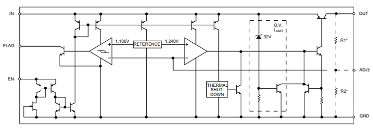
A voltage regulator has three main components, i.e., pass element, error amplifier, and reference voltage source. Typically pass element is an N-channel or P-channel FET, but in MIC29302 voltage regulator it is a PNP transistor. The input voltage is applied to the PNP transistor which is connected to the error amplifier. This transistor operates in the linear region/Active region to reduce the input voltage down to the required output voltage. Error amplifier senses the resulting output voltage and compares it to the reference voltage. The error amplifier changes the transistor to the appropriate operating point to ensure that the output is at the correct voltage. When the input voltage changes, the error amplifier modulates the transistor to maintain a constant output voltage.
Block diagram of MIC29302 voltage regulator IC is given below.

This is how LDO regulator or Low Dropout Regulator Circuit works.
Check the demonstration video given below.


