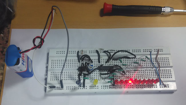
You must have seen different kinds of decoration lighting patterns. In this LED chaser circuit, we have created an interesting LED blinking pattern by using a 555 timer IC and Counter IC CD 4017.
Required Components
- CD 4017 Counter
- 555 Timer IC
- 150, 1K, 10K Resistors
- 10K Variable Resistor
- 10uf, 100nF capacitor
- Breadboard
- 9 Volt Battery
- LED
Circuit Diagram and Explanation
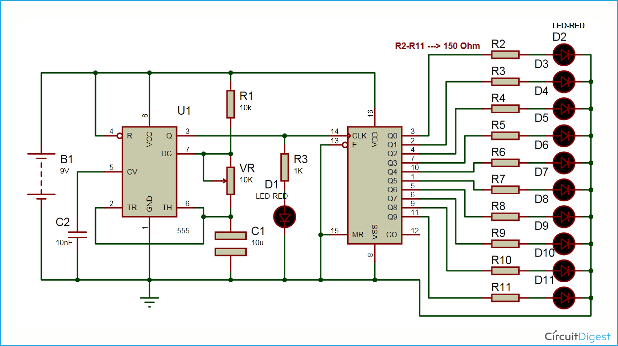
When we power the circuit, LEDs start glowing one by one for a defined time period. Means first LED Q1 glows and then Q2 glows and Q1 turned OFF and then Q3 glows and Q2 turned OFF and so on. When we change resistance of variable resistor then speed of LED’s increase. Because frequency of 555 timer increases and this increases frequency signal is directly connected to counter’s trigger pin. So that counter changes its state faster.
555 timer frequency formula:
The charge time (output HIGH) is given by :
T1 = 0.693 (R1 +VR) C1
The discharge time (output LOW) by :
T2 = 0.693 (R2) C1
Thus the total period T is given by :
T = T1 + T2 = 0.693 (R1 + 2VR) C1
The frequency of oscillation is:
F= 1/T
F=1.44/(R1+2VR)C1
The main part of this LED chaser circuit diagram is 555 timer IC which generates some variable frequency. 555 timer IC is a general purpose IC which can be configured in some different modes like Astable, Monostable and Bistable. Here in this project we configured 555 timer as an Astable multivibrator in which both the stages of signal are unstable. Some time we call frequency generator also. Here we use output signal of this Astable multivibrator to trigger IC CD 4017 counter to change its state to perform desired task.
Here we have connected 555 timer IC in Astable mode for generating a trigger pulse of some time period. A variable resistor is connected for changing the cycle frequency of 555 timer’s output. A CD4017 counter IC is also connected with this circuit for lighting LEDs. 10 red LED’s are connected to Q0-Q9 pin (pin 3) through 150 ohm resistor. MR pin (pin 15), enable or clock inhbit pin (pin 13) is directly connected with ground and Clock pin of counter directly connected with output pin of 555 Timer. (Also see: Heart Shape Serial LED Flasher)
Comments
about a circuit
i need a circuit with 8 leds that switching on one after the another while the past ones lighting,
then off the leds one after the another from the beginning end,can you help me ??
i need a circuit with 8 leds that switching on one after the ano
Hi Mate, the answer is NO. The 4017 is a digital IC. Either on or off for each sequence on each output. It rises to the positive value, then turns off. You could use a set of diodes and capacitors to achieve your goal, though it would be expensive for what you want to do. Better off going for a Linear IC (LM 1370 I think, though I am rusty) It is basically a volume indicator chip that drives a bar display of LED's . It can be done using a charge pump effect using a NE 555 and a capacitor.
If you require further info, just contact me.
LED sequencing
Could be done, but not with a decade counter. You'd need a shift register (such as a 74194) with logic gates to arrange the proper input from the output.
Use its CO (carry out pin -12
Use its CO (carry out pin -12) to multiplex the other 4017 chip, check this for detail about 4017 Toggle Switch
I builded the circuit but it
I builded the circuit but it doest work like thw one in the video . only a led gets turned on even when i change variable resistor value, any tip?
Nice little project.
Nice little project.
May I ask if it's possible to connect 2 LEDs to each Q (in parallel - with appropriate resistors), so that 2 LEDs glow at the same time?
Yes you can connect two LEDs,
Yes you can connect two LEDs, it should work. But if you connect something which draws more power from Q then it may create problem. Check datasheet of CD4017 for power output from Q.
Is there a way to incorporate
Is there a way to incorporate the dancing LED circuit into this so the LEDS flash to the beat of music while simultaneously counting/chasing?
I hope you still answer
I hope you still answer
I have a strip of LED's that I would like to use in this circuit. They are DC12V LEDs tough.
To be more specific, I'm doing a project for a car turn signal that sweeps in 1 direction. The Source is 12v. Any way I can change around the circuit to able to do this and use the LED's I have? I wouldn't mind different LED's but I need them to be bright. Thanks in advance!
Lights blink instead of chase
Not sure but lights stay on then turn pot 10 k clockwise and lights flicker then blink extremely fast?
In parts list is says 100 nf CApacitor but on the schematic shows 10nf.
Also does it matter for the 10uf if electronic ?
Thanks
hi,how many volts are 10k,1k
hi,how many volts are 10k,1k and 150k
Current limiting resistors
There's no point in having a current limiting resistor for each LED. The IC will only supply power to one LED at a time, so each LED can be connected direct to the IC with a single resistor between the common LED cathodes and ground.


where do you put the wires