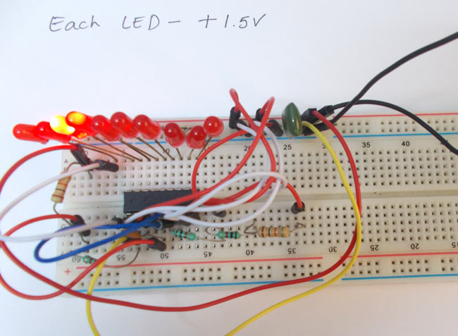
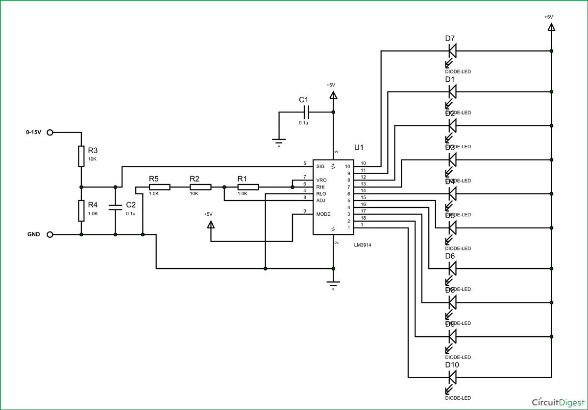
Here we are going to design a simple voltmeter. It’s simple because it includes only one IC chip - LM3914. LM3914 is a chip which drives 10 LED based on linear input voltage value.
The IC provides a decimal output by lighting the necessary LED based on the value of input voltage. The maximum measuring input voltage varies depending on reference voltage and supply voltage, we will discuss that in the later part of the article.
This chip can be modified for battery protection circuit, Ammeter circuit, etc. but here we are using it for the voltmeter. LM3914 is a 10 stage voltmeter that means it shows variations in 10 bit mode. The chip senses the measuring input voltage as a parameter and compares it with reference, every time the voltage crosses the certain part of reference the corresponding LED glows.
The chip is programmed to drive LED directly, so there is no additional resistance required.
Components
Power supply (5v)
1K resistor (3pieces)
10K resistor (2pieces)
LM3914 IC
10 LEDs
0.1µF Capacitor (2 pieces).
Breadboard and Connecting wires
Circuit Diagram and Working
The internal circuit of LM3914 is shown in below figure:
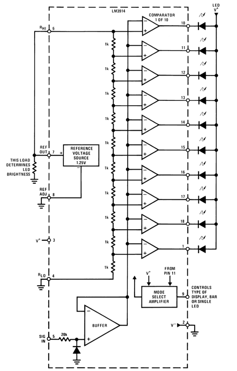
As discussed the LM3914 is a 10 stage measuring unit. This is shown in above internal circuit. LM3914 is basically a combination of 10 comparators. Each comparator is an op-amp, with gaining reference voltage at its negative terminal.
Now the important thing here is that the measuring voltage cannot be higher than reference voltage or the chip supply voltage. This must always be kept in mind. For achieving a higher measuring voltage keeping the input constant we are going to use resistance voltage divider circuit. It simply divides the voltage based on resistors.
Consider the circuit formed by network shown in figure:
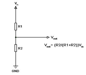
So with input voltage 15V, R1 = 11K, R2 = 1K we have Vout = 15(1/11) =1.5V (approximately).
The reference voltage is chosen based on requirement. The reference value must be the maximum measuring voltage we are going to apply to the chip. If we are measuring variable voltage with peak voltage of 20v we should chose the reference of 20V.
The reference is chosen by equation:
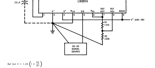
Since we want to measure voltages from 0-15, we need to choose R2 = 11K=10K+1K, R1 = 1K.
With this we have chosen the reference voltage to Vref = 1.25*12 =15V. So we have a maximum input voltage to 15V.
However it is important to remember that higher the reference value greater the step voltage and lower the resolution. Say with reference of 20V we have a step of 2V, any voltage between 2V-4V is not measurable. So with higher voltage we have lesser accuracy.
Since the chip is a 10 stage one and the voltage is from 0-15V we have a 1.5V step. So with every 1.5V increment in measuring voltage, an additional LED glows.
The connections which are done for LM3914 voltmeter circuit are given below:
PIN3 ---------------------------- +5v supply
PIN2-------------------------------- ground
PIN5 ----------------------------- + variable voltage
PIN1,10,11,12,13,14,15,16,17,18 ------------------- connected to LEDS
The measuring level for LED goes as,
+1.5V, +3.0V, +4.5V, +6.0V, +7.5V, +9.0V, +10.5V, +12.0V, +13.5V, +15.0V.
Say the measuring voltage is 10V, sixth LED glows. Say the measuring voltage is 12.5V, ninth LED glows. So with increments of 1.5V, we can measure up to 15V.
[Also check: Voltmeter using AVR Microcontroller]



Need some useful circuits for students help