When a signal goes through a sudden change from base value to higher value and again comes to base value from higher value after some time. It is called a Pulse signal.
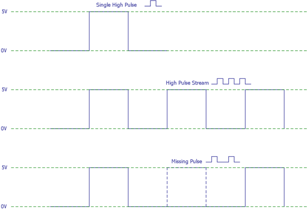
In above image, the first waveform shows a single pulse where the signal is changing from 0 to 5v (low to high) and 5v to 0 (high to low) within a short period of time. Second waveform shows a stream of 5-volt pulses in the signal line. Now when some of the pulses in this pulse chain are failed to occur which are having the predefined interval time, a Missing Pulse Detector Circuit is required to detect those missing pulses. The detector circuit is capable to provide missing pulse notification. Last waveform shown in the image is a missing pulse signal.
Here we will build a Simple Missing Pulse Detector Circuit with few components.
Required Components
1. Breadboard
2. 555 timer IC
3. 2 pcs 10k resistors
4. BC337 NPN Bipolar Junction Transistor
5. Single strand wires for the connection in the breadboard.
6. 0.01uF ceramic disc capacitor
7. 0.1uF ceramic disc capacitor
8.Voltage source of 12 volt / 500 mA (An Adapter can be used)
We need few other things to test Missing Pulse Detector Circuit:
1.Any kind of push button (In this project, the tactile switch is used to interrupt the input pulses.)
2.A source which provides continuous and stable pulses.
It can be a function generator or any kind of square wave or triangular wave source.
3.An oscilloscope to measure the output.
555 Timer IC
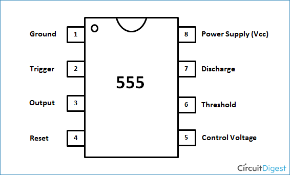
555 Timer IC is a classic timer IC which can be used in many kinds of timing related applications, check all the 555 Timer Circuit here. This is an 8 pin IC. The pin diagram of the 555 timer IC is shown in the below image.
BC337 NPN Transistor
Transistor BC337 is an NPN bipolar junction transistor. It is not necessary to specifically use this transistor here, any NPN transistor can be used. The transistor BC337 consists of 3 pins, base, emitter, and collector as shown in below image:

Circuit Diagram
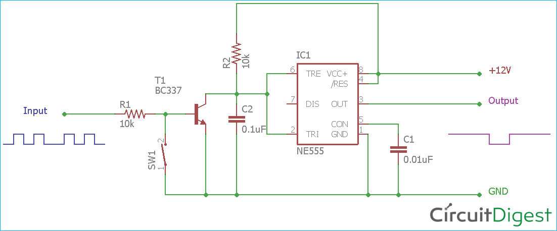
Schematic for Missing Pulse Detector Circuit is shown below:
Here the input is connected to the base of BC337 transistor through a 10k resistor. The 555 timer IC connections are also shown in the schematic. The Capacitor C1 is connected in parallel of the transistor T1. The switch SW1 is used for the testing purpose and to provide a missed pulse.
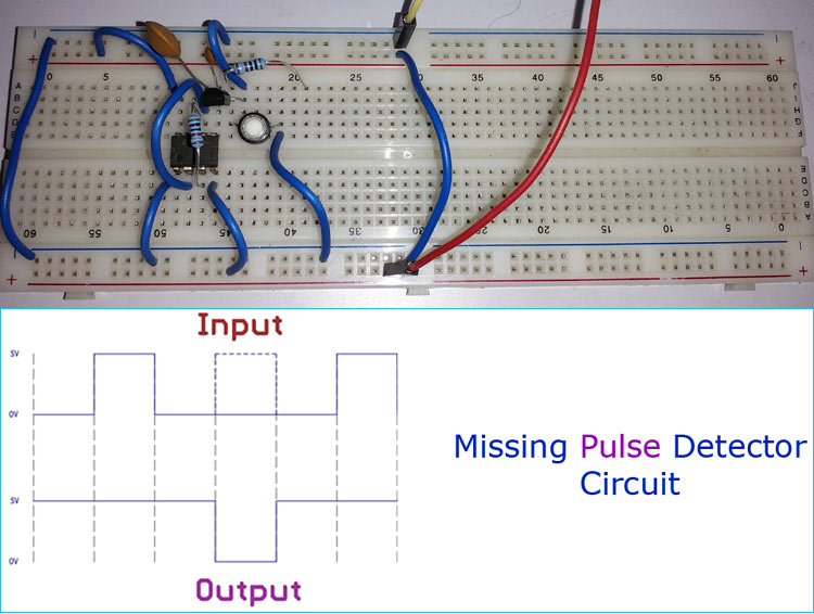
Circuit is constructed on breadboard as shown in below image:

Working of Missing Pulse Detector Circuit
555 Timer iC is configured as a monostable pulse generator. 555 IC requires a RC oscillator to generate the pulses, which is formed using resistor R2 and capacitor C1. Values of R2 and C1 determines the time period in monostable mode. Transistor BC337 is connected across the capacitor C1. Input signal is directly connected to the trigger pin of the timer IC 555 and also connected to the transistor by using a single 10k base resistor.
When the input signal does not provide any missing pulse, the timer IC 555 provides a square wave across the output.
Now a missing pulse arrives, the transistor T1 gets turned on, and as the capacitor C1 is connected across the transistor, it gets discharged by the BC337. During this discharge time, RC oscillator fails to provide the perfect timing interval to the IC 555. Hence, the output remains high.
Values of resistor R2 and capacitor C1 provide the timing control of the circuitry.
Testing of Missing Pulse Detector Circuit
To test the circuit, a signal source is required which provides continuous pulses. Here, the calibration point of the oscilloscope is used for the input signal source purpose.
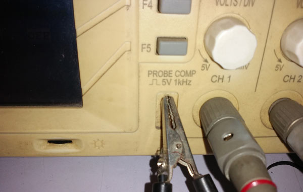
In the above image, the calibration point of the oscilloscope is shown which provide 1Khz square wave in five volts amplitude.
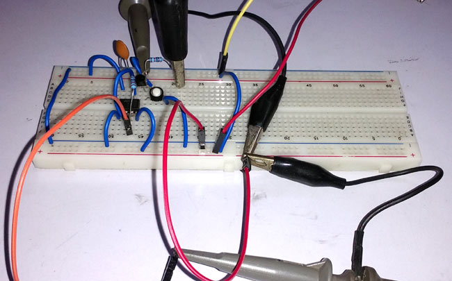
To interrupt or to miss the input pulses, a tactile switch is used which is connected to the Transistor BC337 base and to the ground.
Whenever the tactile switch is being pressed, the base of the BC337 transistor is being shorted with the ground. Due to this, the transistor turns off and the capacitors C1 gets charged.
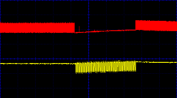
In the above image, the oscilloscope is providing two signals, Red one is input and Yellow one is output. When the switch is pressed, the pulses get missed and the circuit provides square wave at that missed pulse time duration.
You can further check the below video to see input and output waveform in the oscilloscope:
Complete working of the Missing Pulse Detector Circuitry is shown in the video given at the end.
Applications
Missing pulse generator circuit is an excellent application of the classic 555 timer IC. It can trigger an alarm or notify the user when there is some halt or interruption in some process.
1. Many electronics fan system provides continuous pulses during the operation. This circuit can easily determine and trigger the alarm if the fan has been stopped or not working as it should be.
2. In the medical field, the missing pulse detector circuit is used with heartbeat monitoring devices. This could alarm the doctors for abnormalities in the heartbeat.
3. This circuit is also very useful to detect a loss in alternating current supply.
4. It can also be used for half wave or full wave detection in various signal source measuring related operation.
5. In the industrial field where rapid detection is required, a missing pulse detector can be used.

