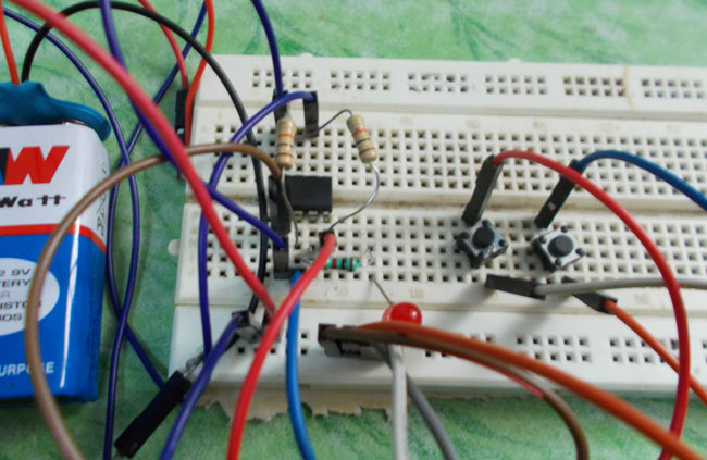
All the embedded systems have memory to store data. These memory are made up of flip-flops, these flip-flops store the data in the form of bits. Each flip flop is can store one bit. So for eight flip-flops we will have 8 bit memory. This memory is used to store programs or to access the program. There are different type of flip flop here we are going o talk about SR flip-flop.
In a 555IC timer there a SR (Set Reset) flip-flop, so the timer can be arranged to store one bit of data. This is what we are going to do here. We use the timer to store a single bit of data.
Circuit Components
- +5 to +12 supply voltage
- 555 IC
- 10KΩ (2pieces), 1KΩ resistors
- Buttons (2 pieces)
- LED,
- 100µF capacitor (not a compulsory, connected in parallel to power)
Circuit and Working Explanation
The circuit diagram of 555IC based one bit memory cell is shown in above figure. Here we are using the flip-flop present in the timer as we discussed earlier.
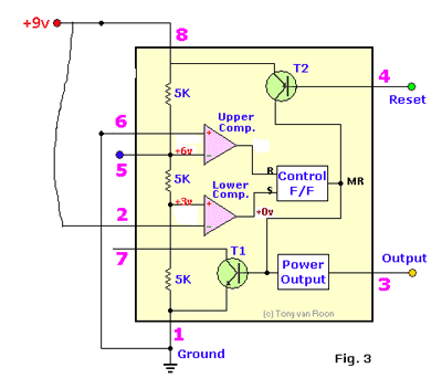
Now consider all the components are connected as shown in the circuit diagram and the power is turned on. Since the threshold pin is connected to power through 10K resistor, the second comparator output will be low. This signal is fed to the second SET pin of the flip-flop inside the timer.
As shown in below figure the flip-flop gets low signal at the set pin of the flip flop.

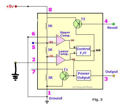
Because of this, the flip-flop will store ZERO in its memory and so the output will be low. As for the low output the LED will be off. Now consider the set button is pressed, then the threshold pin is directly gets connected to ground. This is shown in below figure. Because of this, there will be a higher potential at the positive terminal of second comparator, so the second comparator puts out a positive high signal.
This positive high signal is driven to Flip-flop set pin and so the flip-flop store ONE in its memory and so the Q output will be high, this Q output enables the timer output to go high. So now the LED glow to tell ONE is stored in the flip-flop.

ONE is presently stored in flip-flop memory, now as we press the reset button the PNP transistor in the internal diagram gets turned on. By this there will be a high signal MR (Master Reset).
This master reset when goes high the flip-flop stored bit gets erased. That is the flip-flop pulled down to low. As the flip-flop goes low the output goes low. So the LED will now go off. This is how a timer stores one bit of data in its flip-flop.


