Protection circuits are vital for any electronic design to be successful. In our previous protection circuit tutorials we have designed many basic protection circuits that can be adapted into your circuit, namely, Over Voltage Protection, Short-Circuit Protection, Reverse polarity protection, etc. Adding to this list of circuits, in this article, we will learn how to design and build a simple circuit for Over-current protection using Op-Amp.
Overcurrent protection is often used in power supply circuits to limit the output current of a PSU. The term “Overcurrent” is a condition when the load draws a large current than the specified capabilities of the power supply unit. This can be a dangerous situation as an over-current condition could damage the power supply. So engineers normally use an over-current protection circuit to cut off the load from the power supply during such fault scenarios thus protecting the load and power supply.
Overcurrent Protection using Operational Amplifier
There are many types of over-current protection circuits; the complexity of the circuit depends on how fast the protection circuit should react during an over-current situation. In this project, we will build a simple over-current protection circuit using an op-amp which is very commonly used and can be easily adapted for your designs.
The circuit we are about to design will have an adjustable overcurrent threshold value and will also have an Auto-restart on failure feature. As this is an op-amp based overcurrent protection circuit, it will have an op-amp as the driving unit. For this project, a general-purpose operational amplifier LM358 is used. In the below image, the pin diagram of LM358 is shown.
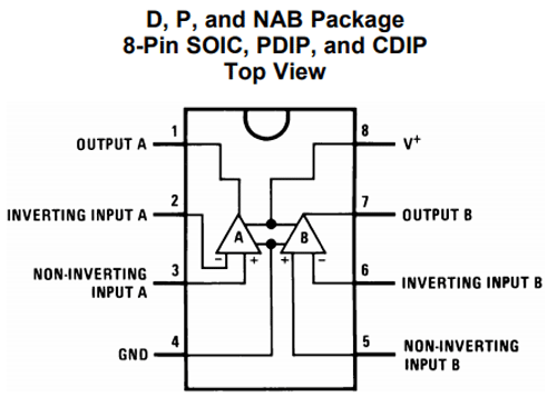
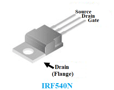
As seen in the above image, inside a single IC package we will have two op-amp channels. However, only a single channel is used for this project. The op-amp will switch (disconnect) the output load using a MOSFET. For this project, an N channel MOSFET IRF540N is used. It is recommended to use proper MOSFET Heatsink if the load current is larger than 500mA. However, for this project, the MOSFET is used without a Heatsink. The below image is the representation of the IRF540N pinout diagram.
To power the op-amp and the circuitry, the LM7809 linear voltage regulator is used. This is a 9V 1A linear voltage regulator with a wide input voltage rating. The pinout can be seen in the below image
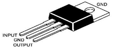
Materials Required:
A list of components required for the overcurrent protection circuit is listed below.
- Breadboard
- Power supply 12V (minimum) or as per the voltage is required.
- LM358
- 100uF 25V
- IRF540N
- Heatsink (as per the application requirement)
- 50k trim pot.
- 1k resistor with 1% tolerance
- 1Meg resistor
- 100k resistor with 1% tolerance.
- 1ohms resistor, 2W (2W maximum of 1.25A load current)
- Wires for breadboard
Overcurrent Protection Circuit
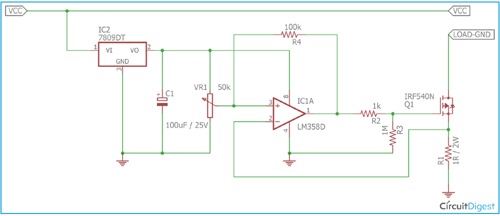
A simple overcurrent protection circuit can be designed by using an Op-Amp to sense the overcurrent and based on the result we can drive a Mosfet to disconnect/connect the load with the power supply. The circuit diagram for the same is simple and can be seen in the below image
Overcurrent Protection Circuit Working
As you can observe from the circuit diagram, the MOSFET IRF540N is used to control the load as ON or OFF during the normal and overload condition. But before turning off the load, it is essential to detect the load current. This is done by using a shunt resistor R1, which is a 1 Ohm shunt resistor with a 2 Watt rating. This method of measuring current is called Shunt Resistor Current Sensing, you can also check other current sensing methods which can also be used to detect over current.
During the ON state of the MOSFET, the load current flows through the MOSFET’s drain to source and finally to the GND via the shunt resistor. Depending on the load current the shunt resistor produces a voltage drop across which can be calculated using Ohms law. Therefore let’s assume, for 1A of current flow (load current), the voltage drop across the shunt resistor is 1V as V = I x R (V = 1A x 1 Ohm). So, if this drop voltage is compared with a predefined voltage using an Op-Amp, we can detect overcurrent and change the state of the MOSFET to cut off the load.
The operational amplifier is commonly used for performing mathematical operations like adding, subtracting, multiplication, etc. Therefore, in this circuit, the operational amplifier LM358 is configured as a comparator. As per the schematic, the comparator compares two values. The first one is the drop voltage across the shunt resistor and another one is the predefined voltage (reference voltage) using a variable resistor or potentiometer RV1. RV1 acts as a voltage divider. The drop voltage across the shunt resistor is sensed by the inverting terminal of the comparator and it is compared with the voltage reference that is connected in the non-inverting terminal of the operational amplifier.
Due to this, if the sensed voltage is less than the reference voltage, the comparator will produce a positive voltage across the output which is close to the VCC of the comparator. But, if the sensed voltage is larger than the reference voltage, the comparator will produce negative supply voltage across the output (negative supply is connected across the GND, so 0V in this case). This voltage is sufficient to switch a MOSFET ON or OFF.
Dealing with Transient response/stability problem
But when the high load will be disconnected from the supply, the transient changes will create a linear region across the comparator and this will create a loop where the comparator couldn't switch the load ON or OFF properly and op-amp will become unstable. For example, let’s assume, 1A is set using the potentiometer for triggering the MOSFET into the OFF condition. Therefore the variable resistor is set for a 1V output. During a situation, when the comparator detects the voltage drop across the shunt resistor is 1.01V (this voltage depends on op-amp or comparator accuracies and other factors) the comparator will disconnect the load. Transient changes occur when a high load is suddenly disconnected from the power supply unit and this transient increase the voltage reference which invites poor results across the comparator and forces it to operate in a linear region.
The best way to overcome this problem is to use a stable power across the comparator where the transient changes do not affect the comparator’s input voltage and the voltage reference. Not only this, additional method hysteresis needs to be added in the comparator. In this circuit, this is done by the linear regulator LM7809 and by using a hysteresis resistor R4, a 100k resistor. LM7809 provides a proper voltage across the comparator so that the transient changes across the power line do not affect the comparator. C1, the 100uF capacitor is used for filtering the output voltage.
The hysteresis resistor R4 feed a small portion of the input across the output of the op-amp which creates a voltage gap between the low threshold (0.99V) and the high threshold (1.01V) where the comparator changes its output state. The comparator does not change the state immediately if the threshold point is met, instead of that, to change the state from high to low, the sensed voltage level needs to be lower than the low threshold (for example 0.97V instead of 0.99V) or to change the state from low to high, the sensed voltage needs to be higher than the high threshold (1.03 instead of 1.01). This will increase the stability of the comparator and reduce false tripping. Other than this resistor, R2 and R3 are used for controlling the gate. R3 is the Gate pull-down resistor of the MOSFET.
Overcurrent Protection Circuit Testing
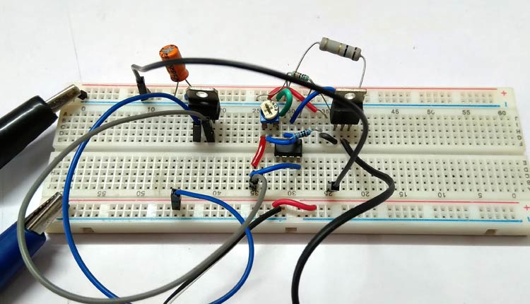
The circuit is constructed in a breadboard and tested using Bench Power supply along with a variable DC Load.
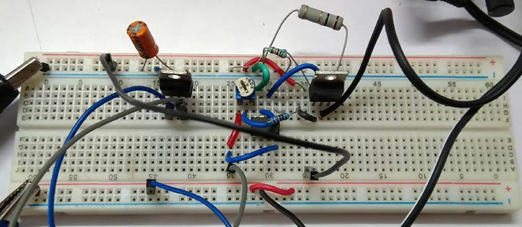
The circuit is tested and the output was observed to successfully get disconnected at different values set by the variable resistor. The video provided at the bottom of this page shows a complete demonstration of overcurrent protection testing in action.
Overcurrent Protection Design Tips
- RC snubber circuit across the output could improve the EMI.
- Larger heat sink and specific MOSFET can be used for the required application.
- Well constructed PCB will improve the stability of the circuit.
- The Shunt Resistor wattage is needed to be adjusted as per the power law (P = I2R) depending on the Load Current.
- Very Low-value resistor in milli-ohms rating can be used for a small package but the voltage drop will be less. To compensate with the voltage drop an additional amplifier with proper gain can be used.
- It is advisable to use a dedicated current sense amplifier for accurate current sensing related issues.
Hope you understood the tutorial and enjoyed learning something useful from it. If you have any questions please leave them in the comment sections or use the forums for other technical questions.

