Recently we thought of building a simple FM receiver circuit, so like always we started googling for possible circuits that can be used to fulfill our requirements, and as expected we found a lot of circuits on the internet, but the question remains how good or useful will they be when we put those circuits to the test. Because just like us we found a lot of people trying to get these circuits to work but fail, and a lot of discussion forums are filled with questions "Do these simple DIY FM Receiver circuits really work?"
So in this tutorial, we did just that by building a few circuits on a piece of perf board and testing each circuit to see their working and what can be done to improve this, and in the end, we will let you know all the details.
Now if you want to save time, you can straight away buy the RDA5807 FM receiver module and use it for your project, we have already built a Voice Controlled FM Radio using Arduino and Google Assistant and Arduino Based FM Radio using RDA5807. You can check those projects out if you want to learn more about those projects or you can check the simple FM transmitter circuit built using basic electronic components like transistors, capacitors, coil etc.
The Two Transistor FM Radio or the Direct (TRF) FM Receiver
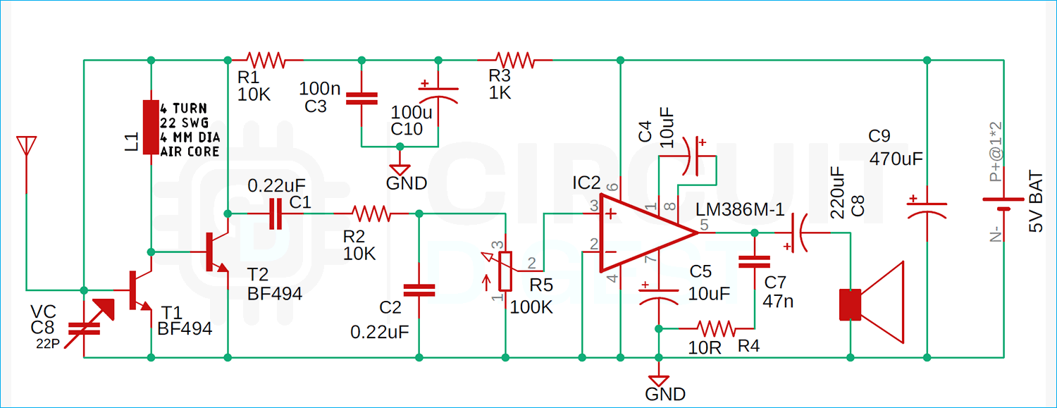
Most of the circuits we have found on the internet have one thing in common, and that is they all have a two-transistor configuration. And for our first circuit, we tried something similar.
Not only it receives the FM signal it also amplifies the received signal with the help of an lm386 OP-Amp IC to drive a speaker. This is by far one of the most complicated circuits made with very few components. The transistors BF495(T2) with Inductor L. Capacitor VC, and along with T1 makes the construction for the Colpitts oscillator.
In this circuit, the trimmer VC sets the resonance frequency of the circuit. By adjusting the variable capacitor the resonance frequency changes and we can tune the circuit anywhere between 88 and 108MHz. The message signal that is received through the circuit is extracted through the resistor R1 and then it is fed to the audio amplifier over a 220nF coupling capacitor (C1). This circuit is so designed that you can tune the radio receiver with the help of the Variable Capacitor. The value of the variable capacitor is adjusted to 20pF because variable capacitors with this value are readily available.
The coil used in the circuit is a simple air core inductor made with 4 turns of 22 SWG copper wire with the core having a 4mm internal diameter. When the required number of turns is reached the coil is cylindrical. The coil can be taken so that the high frequency signal can be reached by the receiver. Finally, the capacitors C3 (100nF) and C10 (100µF, 25V), together with R3 (1k), comprise a band-pass filter for very low frequencies, which is used to separate the low-frequency signal from the high-frequency signal in the receiver.
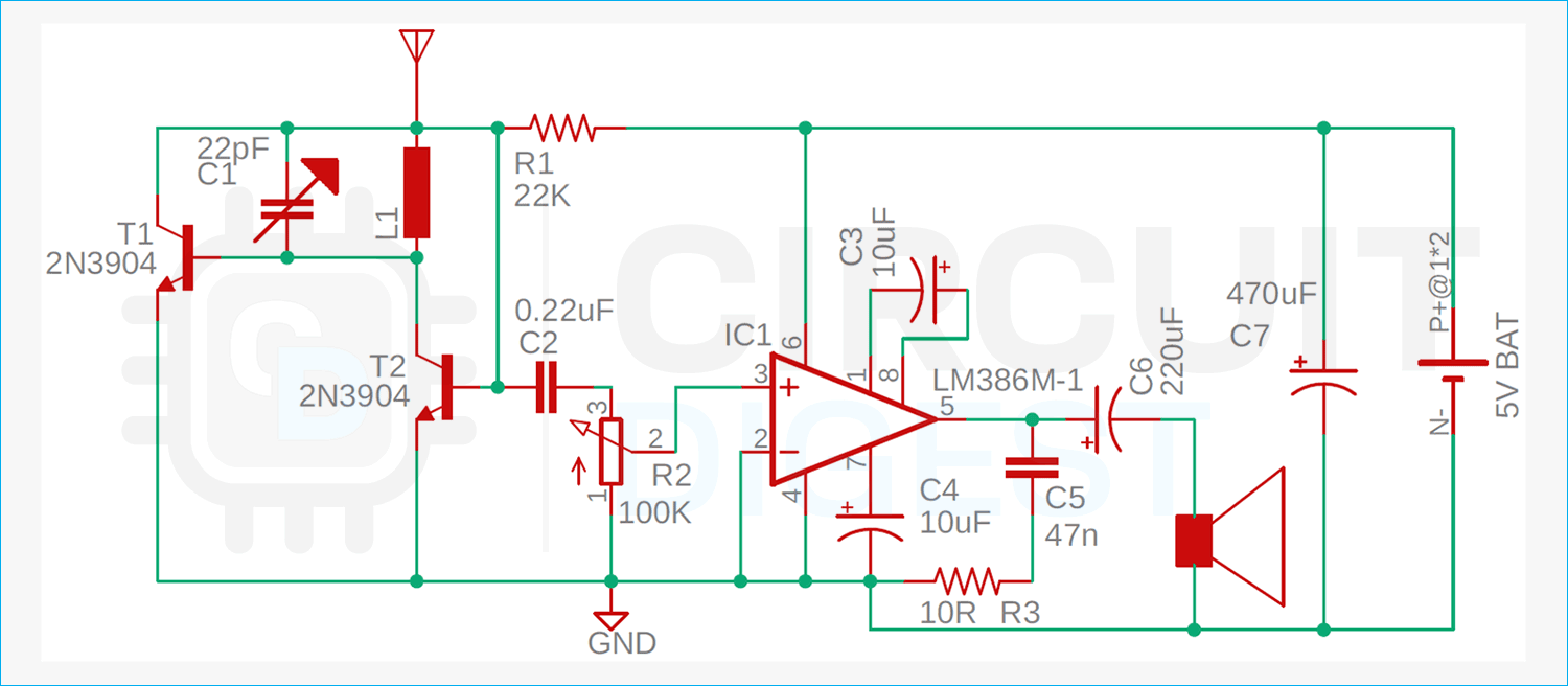
FM Radio Receiver with 2N3904 Transistors
Next, this is another FM radio receiver circuit that has a two-transistor configuration. But like the previous circuit, this circuit uses two 2N3904 general-purpose transistors to generate the resonance frequency
While testing the above circuit we have observed that this circuit works best between 3.3 to 3.5 Volt range. The working of this circuit is very simple, the resonance frequency of the circuit is generated by the L1 and C1 in the circuit, LC together is called a tank circuit that is able to produce high frequency oscillation that is required to generate FM signal, when the capacitor gets fully charged then it dumps it to the inductor, the inductor charges up and builds up its magnetic field when the magnetic field collapses the energy gets back to the capacitor and the process repeats infinitely the resonance frequency of the circuit can be easily found out by using a simple formula. In the next section, we will be looking at that
Building an Inductor and Calculating the inductance
The most important part of any FM radio circuit board is the inductor and in this section, we will learn how to build an inductor. If you look at the first circuit, it says it's 4 turns in a 4mm diameter air core with 22 AWG copper wire. Once we have built the inductor we can use the formula shown below to calculate the inductance.
L= (d^2 * n^2)/(18d+40l)
Where,
L= is inductance in microHenries (µH)
d= coil diameter in inches
l= is coil length in inches
N = Number of turns
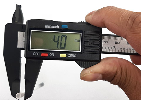
Now as we know the formula, we need to measure the diameter of the coil to calculate the inductance. If you look at the first schematic you can see that the instruction to make the inductor is given. Its 4 turns of 22 SWG wire with a 4mm diameter air core. For the 4mm diameter, we are using a refill from a gel pen. As you can see from the image below the refill from the pen is exactly 4mm.
Now once we have the 4mm diameter cylindrical, we will wrap our 22 SWG wire around the pen refill and make the inductor. Once the inductor was made it looks like the image shown below,
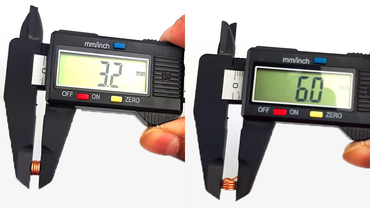
Now we will measure the length and the diameter of the coil and as you can see from the image above we have a coil diameter of 6mm and the length of the coil is 3.2mm. With this, we have all the parameters to calculate the inductance of the coil. Now if we calculate the inductance by using the formula given we can calculate the value is
L = 0.0961 uH
You can do the calculation by putting the values in the calculator or you can use the Air Core Inductor Coil Inductance Calculator website to calculate the inductance which makes the process so much easier.
Testing FM Radio Receiver Circuit Board
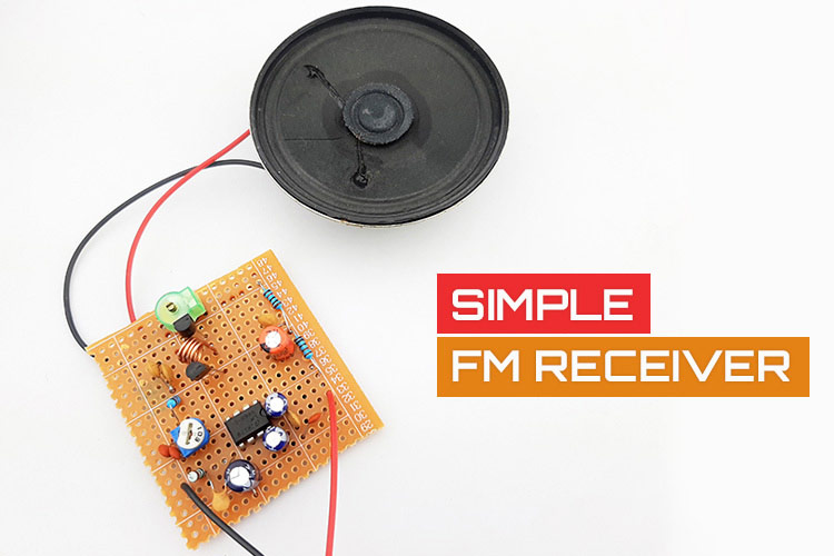
As you can see from the above two schematics we have found two promising circuits on the internet and we tried to test both circuits, the circuit made with BF494 transistors performed somewhat better than the circuit made with 2N3904 transistors. You can also see that we have made the two circuits in two different places because we don't want to add in noise from any other components.
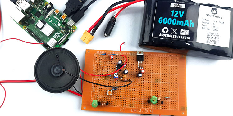
As you can see the test setup shown in the above image where we are powering the circuit with a 12V battery. Once the circuit was powered on we turned the variable capacitor to try to tune the circuit to capture local FM radio stations, but the circuit wasn't able to pick up anything.
After checking and trying to figure out what the problem was we used a Raspberry PI to build a FM transmitter and check to see if the circuit was working or not. And to our surprise, the circuit worked but the audio was not audible and the sound.
In conclusion, we can say that it's absolutely not worth it to waste time on building and testing this kind of simple FM radio receiver circuit because it's not made to be used for day to day application. And it's recommended to use a proper IC based FM radio receiver module if you intend to use this for day to day application. If you are looking for some FM Radio Receiver IC Then the RDA5807 or TEA5767 are some of the ICs which are easily available in the market and you can make simple FM receiver circuit with easily available parts and schematics.

