The Wireless Electricity Transfer concept is not new. It was first demonstrated by Nikola Tesla in the year 1890. Nikola Tesla introduced electrodynamics induction or resonant inductive coupling by lighting up three light bulbs from the distance of 60 feet from the power source. We have also built a Mini Tesla Coil to transfer the energy.
Wireless Electricity Transfer or WET is a process to supply power through an air gap without using any wires or physical link. In this wireless system, the transmitter device generates a time-varying or high-frequency electromagnetic field, which transmits power to receiver device without any physical connection. The receiver device extracts power from the magnetic field and supplies it to electrical load. Therefore, to convert the electricity to an electromagnetic field, two coils are used as transmitter coil and receiver coil. The transmitter coil is powered by alternating current and creates a magnetic field, which is further converted into a usable voltage across the receiver coil.
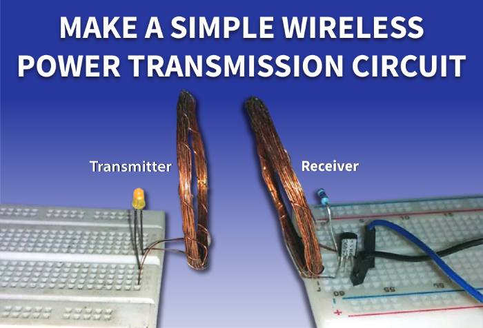
In this project, we will build a basic low powered wireless transmitter circuit to glow an LED.
Components Required
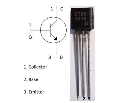
- Transistor BC 549
- LED
- Breadboards
- Hook up wires
- 1.2k resistors
- Copper wires
- 1.5V battery
Circuit Diagram
The schematics, for transferring electricity wirelessly to glow an LED, is simple and can be seen in the below image, It has two parts, Transmitter, and the receiver.

At Transmitter side, the coils are connected across the collector of the transistor, 17 turn on both sides. And the receiver is constructed using three components- transistor, resistor, and a center tapped air core inductor or a copper coil. Receiver side has an LED connected across the 34 turns copper coil.
Construction of the Wireless Power Transmission Circuit
Here the transistor used is NPN Transistor, any basic NPN transistor can be used here like BC547.
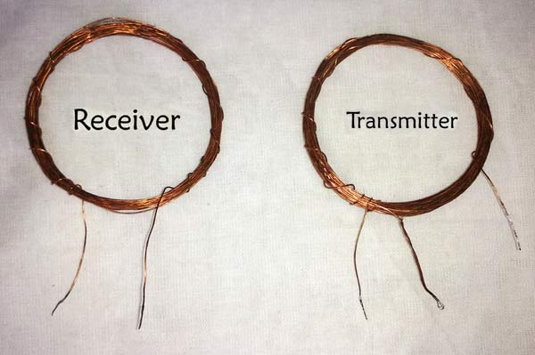
Coil is the crucial part in wireless energy transfer and should be built carefully. In this project, the coils are made using copper wire of 29AWG. Center tapped coil formation is done on the transmitter side. is used and a cylindrical coil wrapper like PVC pipe is required to wind the coil.
For the transmitter, wind the wire till 17-turns, then the loop for center tap connection and again make 17 turns of coil. And for the receiver, make a 34 turns of coil winding without the center tap.
 coil")
Working of the Wireless Electricity Transfer Circuit
Both the circuits are constructed on the breadboard and powered using a 1.5V battery. The circuit can’t be used for more than 1.5 volt power supply as transistor may heat up for excessive power dissipation. However, for more rating, additional driving circuits are needed.
This wireless electricity transmission is based on the Inductive coupling technique. The circuit consists of two parts- Transmitter and Receiver.
In transmitter section, the Transistor is generating high-frequency AC current across the coil and the coil is generating a magnetic field around it. As the coil is center tapped, the two sides of the coil start to charge up. One side of the coil is connected to the resistor and another side is connected to the collector terminal of NPN transistor. During the charging condition, the base resistor starts to conduct which eventually turns on the transistor. The transistor then discharges the inductor as the emitter is connected with the ground. This charging and discharging of the inductor produces a very high frequency oscillation signal which is further transmitted as a magnetic field.
On the receiver side, that magnetic field is transferred into the other coil, and by the Faraday’s law of induction, the receiver coil start producing EMF voltage which is further used to light up the LED.
The circuit is tested on the breadboard with a LED connected across the receiver. Detailed working of the circuit can be seen in the video given at the end.
Limitation of the Circuit
This small circuit can work properly but it has a huge limitation. This circuit is not suitable to deliver high power and has input voltage restriction. The efficiency is also very poor. To overcome this limitation, a push-pull topologies using transistors or MOSFETs can be constructed. However, for better and optimized efficiency, it is better to use proper wireless transmission driver ICs.
To improve the transmission distance, wind up the coil properly and increase the no. of turns in the coil.
Applications of Wireless Power Transmission
Wireless power transfer (WPT) is a widely discussed topic in the electronics industry. This technology is growing rapidly in the consumer electronics market for smartphones and chargers.
There are countless benefits of WPT. Some of them are explained below:
Firstly, in modern power requirement area, WPT can eliminate the traditional charging system by replacing the wired charging solutions. Any portable consumer goods require its own charging system, wireless power transfer can solve this problem by providing a universal cordless power solution for all those portable devices. There are already many devices available in the market with built-in wireless power solution like smartwatch, smartphone etc.
Another benefit of WPT is that it allows the designer to make completely waterproof product. As the wireless charging solution does not need the power port so the device can be made in a way that is water resistance.
It also offers a wide range of charging solutions in an efficient way. The power delivery ranges up to 200W, with very low loss of power transfer.
A major benefit of wireless power transmission is that the product life can be increased by preventing the physical damages due to charger insertion across the connectors or the ports. Multiple devices can be charged from a single dock. Electronics vehicle can also be charged using wireless power transfer during the car is parked.
Wireless Energy Transfer can have huge applications and many big companies like Bosch, IKEA, Qi are working on some futuristic solutions using Wireless power transmission.