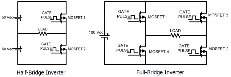
Alternating Current (AC) power supply is used for almost all the residential, commercial and industrial needs. But the biggest issue with AC is that it cannot be stored for future use. So AC is converted into DC and then DC is stored in batteries and ultra-capacitors. And now whenever AC is needed, DC is again converted into AC to run the AC based appliances. So the device which converts DC into AC is called Inverter.
For single phase applications, single phase inverter is used. There are mainly two types of single-phase inverter: Half Bridge Inverter and Full Bridge Inverter. Here we will study how these inverters can be built and will simulate the circuits in MATLAB.
Half Bridge Inverter
This type of Inverter requires two power electronics switches (MOSFET). The MOSFET or IGBT is used for switching purpose. Circuit diagram of the half bridge inverter is as shown in below figure.
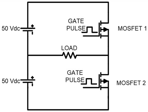
As shown in circuit diagram, input DC voltage is Vdc = 100 V. This source is divided into two equal parts. Now gate pulses are given to the MOSFET as shown in below figure.
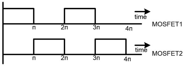
According to output frequency, ON time and OFF time of MOSFET is decided and gate pulses are generated. We need 50Hz AC power, so the time period of one cycle (0 < t < 2π) is 20msec. As shown in the diagram, MOSFET-1 is triggered for first half cycle (0 < t < π) and during this time period MOSFET-2 is not triggered. In this time period, current will flow in the direction of arrow as shown in below figure and half cycle of AC output is completed. The current from the load is right to left and load voltage is equal to +Vdc/2.
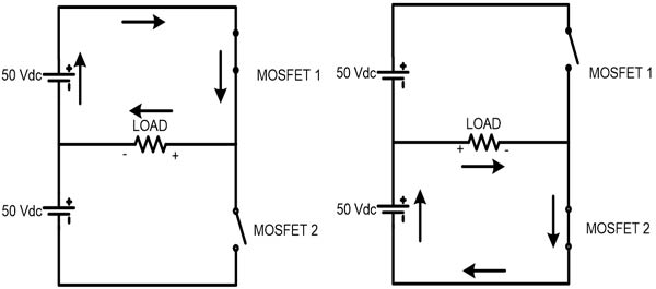
In second half cycle (π < t < 2π), the MOSFET-2 is triggered and lower voltage source is connected with the load. The current from the load is left to right direction and load voltage is equal to -Vdc/2. In this time period, current will flow as shown in figure and the other half cycle of AC output is completed.
Full Bridge Inverter
In this type of inverter, four switches are used. The main difference between half bridge and full bridge inverter is the maximum value of output voltage. In half bridge inverter, peak voltage is half of the DC supply voltage. In full bridge inverter, peak voltage is same as the DC supply voltage. The circuit diagram of full bridge inverter is as shown in below figure.
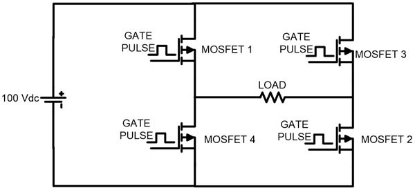
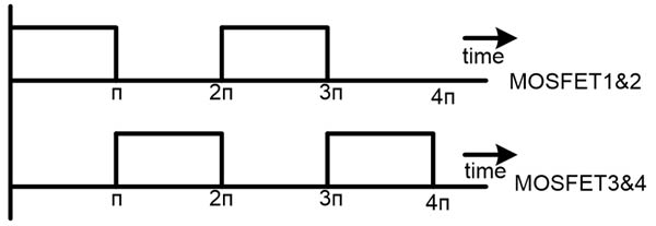
The gate pulse for MOSFET 1 and 2 are same. Both switches are operating at same time. Similarly, MOSFET 3 and 4 has same gate pulses and operating at same time. But, MOSFET 1 and 4 (vertical arm) never operate at same time. If this happens, then DC voltage source will be short circuited.
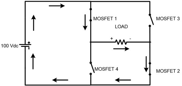
For upper half cycle (0 < t < π), MOSFET 1 and 2 get triggered and current will flow as shown in figure below. In this time period, the current flow from left to right direction.
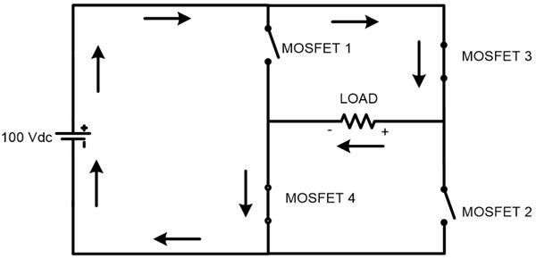
For lower half cycle (π < t < 2π), MOSFET 3 and 4 get triggered and current will flow as shown in figure. In this time period, the current flow from right to left direction. The peak load voltage is same as DC supply voltage Vdc in both cases.
Simulation of Half-Bridge Inverter in MATLAB
For simulation add elements in model file from Simulink library.
1) 2 DC source – 50V each
2) 2 MOSFET
3) Resistive load
4) Pulse generator
5) NOT gate
6) Powergui
7) Voltage measurement
8) GOTO and FROM
Connect all the components as per the circuit diagram. The screenshot of Half Bridge Inverter model file is shown in below image.
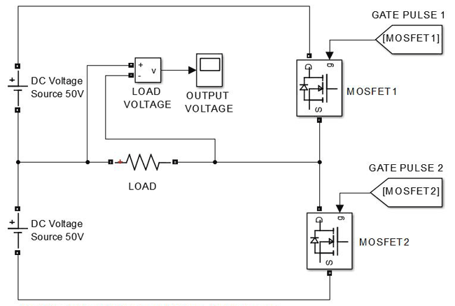
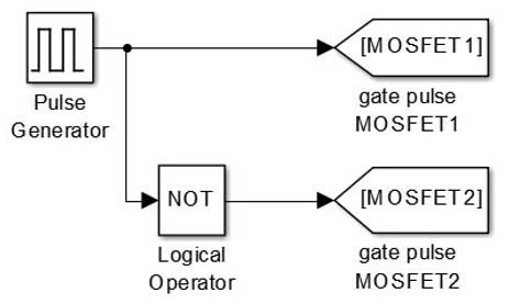
Gate pulse 1 and gate pulse 2 are gate pulses for MOSFET1 and MOSFET2 which is generated from gate generator circuit. The gate pulse is generated by PULSE GENERATOR. In this case, MOSFET1 and MOSFET2 cannot be triggered at same time. If this happens then voltage source will be short circuited. When MOSFET1 is closed, MOSFET2 will be open at that time, and when MOSFET2 is closed MOSFET1 is open at that time. So, if we generate gate pulse for any one MOSFET, then we can toggle that pulse and use for other MOSFET.
Gate Pulse generator
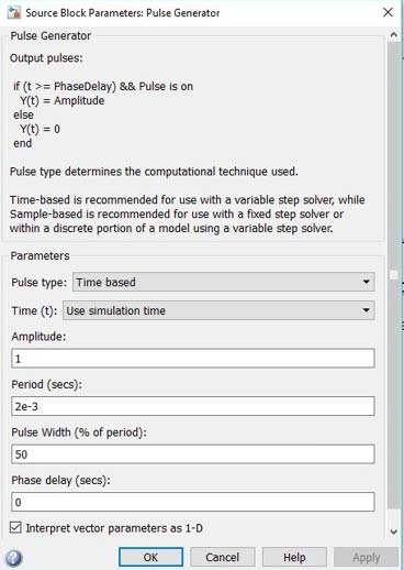
Above image shows the parameter for pulse generator block in MATLAB. The period is 2e-3 means 20 msec. If you need 60Hz frequency output, then period will be 16.67 msec. The pulse width is in terms of percentage of period. It means that, the gate pulse is generated for this area only. In this case, we set this at 50%, it means 50% period gate pulse is generated and 50% period gate pulse is not generated. The phase delay is set 0 sec, means we are not giving any delay to the gate pulse. If there is any phase delay, it means gate pulse will be generated after this time. For example, if phase delay is 1e-3 then gate pulse will be generated after 10msec.
By this way we can generate the gate pulse for MOSFET1 and now we will toggle this gate pulse for and use it for MOSFET2. In simulation, we will use logical NOT gate. The NOT gate inverse the output means it will convert 1 to 0 and 0 to 1. This is how, we can exactly get opposite gate pulse so that DC source will never be short circuited.
In practical, we cannot use 50% pulse width. The MOSFET or any power electrical switch takes small time to turn off. To avoid short circuit of source, pulse width is set around 45% to allow the time for MOSFETs to turn off. This time period is known as Dead Time. But, for simulation purpose, we can use 50% pulse width.
Output waveform for Half-Bridge Inverter
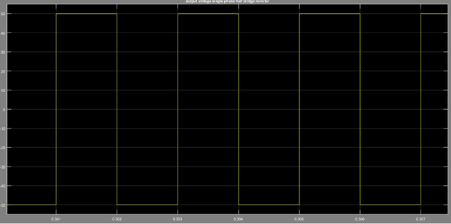
This screenshot is for the output voltage across the load. In this image, we can see that, the peak value of load voltage is 50V, which is half of DC supply and frequency is 50Hz. For complete one cycle, required time is 20 msec.
Simulation of Full Bridge Inverter in MATLAB
If you get output of half bridge inverter, then it is easy to implement the full bridge inverter, because most of all things remain the same. In full bridge inverter also, we need only two gate pulses which is same as half bridge inverter. One gate pulse is for MOSFET 1 and 2 and inverse of this gate pulse is for MOSFET 3 and 4.
Elements required
1) 4 – MOSFET
2) 1 DC source
3) Resistive load
4) Voltage measurement
5) Pulse generator
6) GOTO and FROM
7) powergui
Connect all the components as shown in below screenshot.
Output wave form for Full Bridge Inverter
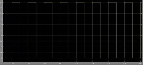
This screenshot is for output voltage across the load. Here we can see that, the peak value of load voltage is equal to the DC supply voltage that is 100V.
You can check the complete walk through Video of how to build and simulate the Half Bridge and Full Bridge Inverter in MATLAB below.


Arduino programme needed.