The term digital in electronics represents the data generation, processing or storing in the form of two states. The two states can be represented as HIGH or LOW, positive or non-positive, set or reset which is ultimately binary. The high is 1 and low is 0 and hence the digital technology is expressed as series of 0’s and 1’s. An example is 011010 in which each term represents an individual state. Thus, this latching process in hardware is done using certain components like latch or Flip-flop, Multiplexer, Demultiplexer, Encoders, Decoders and etc collectively called as Sequential logic circuits.
So, we are going to discuss about the Flip-flops also called as latches. The latches can also be understood as Bistable Multivibrator as two stable states. Generally, these latch circuits can be either active-high or active-low and they can be triggered by HIGH or LOW signals respectively.
The common types of flip-flops are,
- RS Flip-flop (RESET-SET)
- D Flip-flop (Data)
- JK Flip-flop (Jack-Kilby)
- T Flip-flop (Toggle)
Out of the above types only JK and D flip-flops are available in the integrated IC form and also used widely in most of the applications.
Here in this article we will discuss about SR Flip Flop and will explore the other Flip Flop in later articles.
SR Flip-flop:
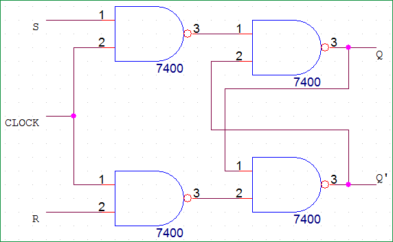
SR Flip-flops were used in common applications like MP3 players, Home theatres, Portable audio docks, and etc. But now-a-days JK and D flip-flops are used instead, due to versatility. SR latch can be built with NAND gate or with NOR gate. Either of them will have the input and output complemented to each other. Here we are using NAND gates for demonstrating the SR flip flop.
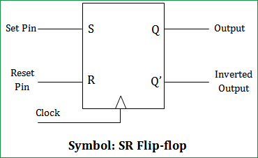
Whenever the clock signal is LOW, the inputs S and R are never going to affect the output. The clock has to be high for the inputs to get active. Thus, SR flip-flop is a controlled Bi-stable latch where the clock signal is the control signal. Again, this gets divided into positive edge triggered SR flip flop and negative edge triggered SR flip-flop. Thus, the output has two stable states based on the inputs which have been discussed below.
Truth table of SR Flip-Flop:
|
CLK State |
INPUT |
OUTPUT |
||
|
Clock |
S’ |
R’ |
Q |
Q’ |
|
LOW |
x |
x |
0 |
1 |
|
HIGH |
0 |
0 |
0 |
1 |
|
HIGH |
1 |
0 |
1 |
0 |
|
HIGH |
0 |
1 |
0 |
1 |
|
HIGH |
1 |
1 |
1 |
0 |
The memory size of SR flip flop is one bit. The S (Set) and R (Reset) are the input states for the SR flip-flop. The Q and Q’ represents the output states of the flip-flop. According to the table, based on the inputs, the output changes its state. But, the important thing to consider is all these can occur only in the presence of the clock signal.
We are constructing the SR flip flop using NAND gate which is as below,
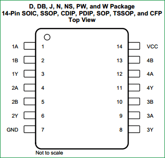
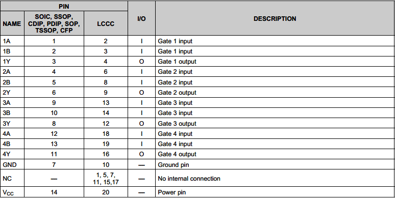
The IC used is SN74HC00N (Quadruple 2-Input Positive-NAND Gate). It is a 14 pin package which contains 4 individual NAND gates in it. Below is the pin diagram and the corresponding description of the pins.
Components Required:
- IC SN74HC00 (Quad NAND Gate) – 1No.
- LM7805 – 1No.
- Tactile Switch – 3No.
- 9V battery – 1No.
- LED (Green – 1; Red – 2)
- Resistors (1kὨ - 2; 220kὨ -2)
- Breadboard
- Connecting wires
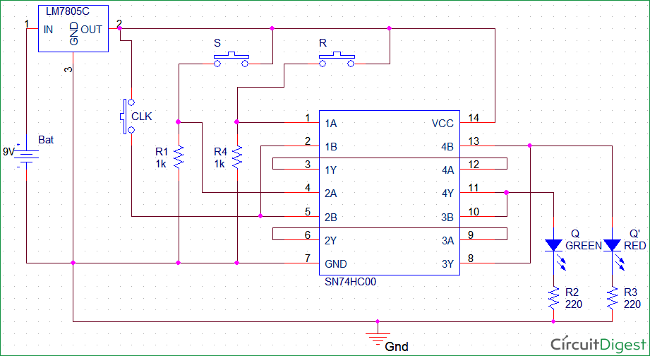
SR Flip-flop Circuit Diagram and Explanation:
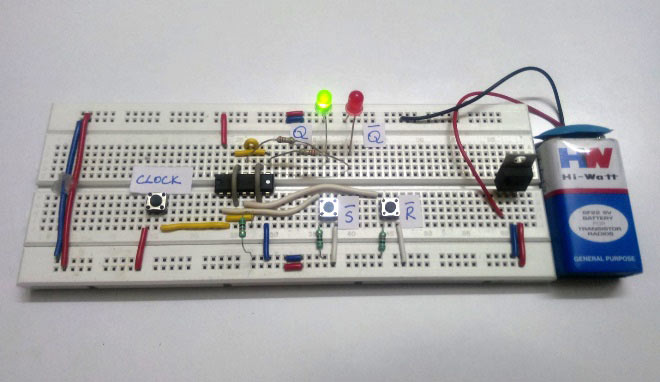
Here we have used IC SN74HC00N for demonstrating SR Flip Flop Circuit, which has four NAND gates inside. The IC power source has been limited to MAXIMUM OF 6V and the data is available in the datasheet. Below snapshot shows it.

Hence, we have used a LM7805 regulator to limit the supply voltage and pin voltage to 5V maximum.
Working of SR Flip Flop:
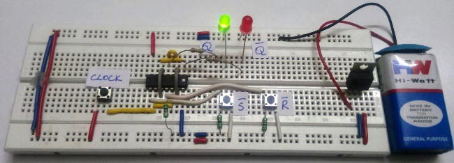
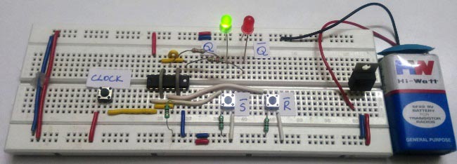
The two buttons S (Set) and R (Reset) are the input states for the SR flip-flop. The two LEDs Q and Q’ represents the output states of the flip-flop. The 9V battery acts as the input to the voltage regulator LM7805. Hence, the regulated 5V output is used as the Vcc and pin supply to the IC. Thus, for different input at S’ and R’ the corresponding output can be seen through LED Q and Q’.
The truth table and corresponding states varies according to the type of construction which can be either using NAND gates or NOR gates. Here, it is done using NAND gates. The pins S’ and R’ are normally pulled down. Hence, default input state will be S’=0, R’=0.
Below we have described the all four states of SR Flip-Flop using SR flip flop circuit made on breadboard.
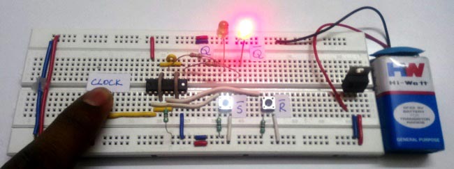
State 1: Clock – HIGH ; S’ – 0 ; R’ – 0 ; Q – 0 ; Q’ – 0
For the State 1 inputs, the RED led glows indicating the Q’ to be HIGH and GREEN led shows Q to be LOW.
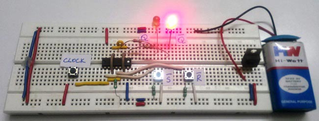
State 2: Clock – HIGH ; S’ – 1 ; R’ – 0 ; Q – 1 ; Q’ - 0
For the State 2 inputs the GREEN led glows indicating the Q to be HIGH and RED led shows Q’ to be LOW.
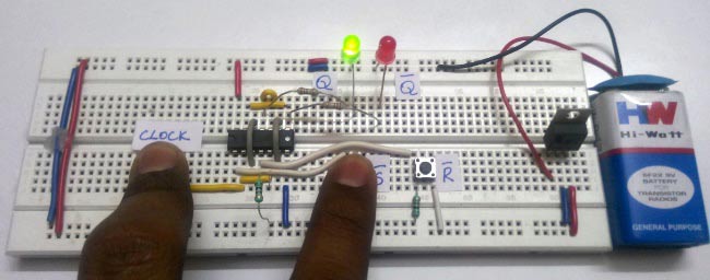
State 3: Clock – HIGH ; S’ – 0 ; R’ – 1 ; Q – 0 ; Q’ - 1
For the State 3 inputs the RED led glows indicating the Q’ to be HIGH and GREEN led shows Q to be LOW.
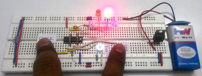
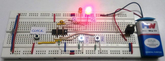
State 4: Clock – HIGH ; S’ – 1 ; R’ – 1 ; Q – 1 ; Q’ - 1
For the State 4 inputs the RED led and GREEN led glows indicating the Q & Q’ to be HIGH. But, the state is not stable practically. The output becomes Q=1 & Q’=0 due to instability and absence of continuous clock.
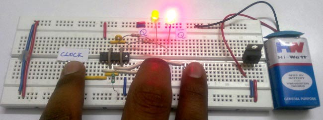



but we have RS latch no flip-flop.the truth table is also associated to previous Q ,Q`.do this flip flop is edge trigger?