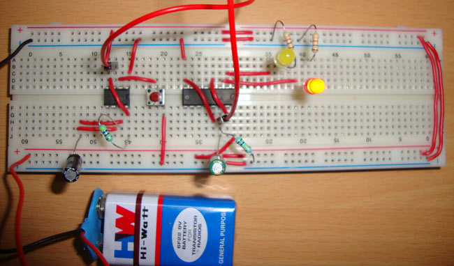
Toggle switch is used to toggle the output between two devices. Means when one device is ON, second device remains OFF and when second device is OFF, first device becomes ON. This toggle of output can be controlled using a PUSH button switch, so you can control two devices using one button. Further you can interface two Relays in place of LEDs to control the two AC appliances. We have mainly used 555 time IC and 4017 IC in this circuit.
This same circuit can be used as PUSH ON/PUSH OFF button circuit, if we remove any of the LED. One button press would ON the LED and another Press would OFF the LED.
4017 IC
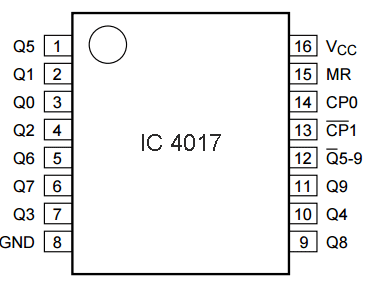
4017 IC is a CMOS decade counter chip. It can produce output at the 10 pins (Q0 – Q9) sequentially, means it produce output one by one at the 10 output pins. This output is controlled through a LOW to HIGH clock pulse at PIN 14 (positive edge triggering). At first, output at Q0 (PIN 3) is HIGH, then with each clock pulse, output advance to the next PIN. Like one clock pulse makes the Q0 LOW and Q1 HIGH, and then the next clock pulse makes the Q1 LOW and Q2 HIGH, and so on. After the Q9, it will start from the Q0 again. So it creates sequential ON and OFF of all the 10 OUTPUT PINs. Below is the PIN diagram and PIN description of 4017:

|
PIN NO. |
PIN Name |
PIN Description |
|
1 |
Q5 |
Output 5: Goes high in 5 clock pulse |
|
2 |
Q1 |
Output 1: Goes high in 1 clock pulse |
|
3 |
Q0 |
Output 0: Goes high at the beginning – 0 clock pulse |
|
4 |
Q2 |
Output 2: Goes high in 2 clock pulse |
|
5 |
Q6 |
Output 6: Goes high in 6 clock pulse |
|
6 |
Q7 |
Output 7: Goes high in 7clock pulse |
|
7 |
Q3 |
Output 3: Goes high in 3 clock pulse |
|
8 |
GND |
Ground PIN |
|
9 |
Q8 |
Output 8: Goes high in 8 clock pulse |
|
10 |
Q4 |
Output 4: Goes high in 4 clock pulse |
|
11 |
Q9 |
Output 9: Goes high in 9 clock pulse |
|
12 |
CO –Carry out |
Used to cascade another 4017 IC to makes it count upto 20, it is divide by 10 output PIN |
|
13 |
CLOCK inhibit |
Clock enable pin, should kept LOW, keeping HIGH will freeze the output. |
|
14 |
CLOCK |
Clock input, for sequentially HIGH the output pins from PIN 3 TO PIN 11 |
|
15 |
RESET |
Active high pin, should be LOW for normal operation, setting HIGH will reset the IC (only Pin 3 remain HIGH) |
|
16 |
VDD |
Power supply PIN (5-12v) |
Components
- CD4017 IC
- 555 Timer IC
- Resistor- 1k, 100k, 470 ohm
- Capacitors- 1uF, 22uF
- 2 LEDs
- Push Button switch
- Power supply 5-9v
Circuit Diagram and Explanation
We now know that 4017 IC output advance with a positive edge clock pulse, so we have used 555 timer IC in Monostable mode, to produce a LOW to HIGH clock pulse. We have connected a button on Trigger PIN 2 of 555 IC, to produce a positive edge pulse with each button press. To trigger the 555 in monostable mode, trigger PIN 2 must be LOW, so we have connected it to the Ground using PUSH button switch. This generated clock pulse at PIN 3 of 555 is given to 4017 IC at PIN 14.
When firstly, power is applied to IC 4017, output at PIN 3 (Q0) is HIGH, where we have connected FIRST LED. When we press the PUSH button, then a LOW to HIGH clock pulse is applied to PIN 14 (first clock pulse) of 4017 and output at Q0 becomes low and PIN 2(Q1) becomes HIGH, where we have connected Second LED. Now this position will remain until the next clock pulse. If we press the Push Button again (second clock pulse), output at Q1 becomes LOW and Q2 becomes HIGH. And because Q2 is connected to the RESET pin 15 of 4017, it will reset the IC and again output at Q0 becomes HIGH (first LED) and Q2 becomes LOW (Second LED). So it works like a toggle switch.
We have also used a RC circuit (22uf capacitor and 100k resistor) at CLOCK PIN 14 of 4017, so that it only counts one clock pulse on each time button is pressed. Otherwise circuit may behave unexpectedly OR it can count two or more pulses because of noise or bouncing effect of Push button.
Comments
Check the datasheet for max
Check the datasheet for max voltage rating of the components used.


Could this circuit work with 10v - 14v dc? ... Could a 2nd 555 chip be used to control the 2nd half of the 4017?
Thanks