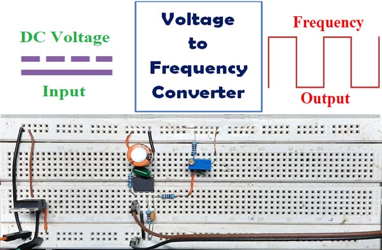
A voltage-to-frequency converter (VFC) is an oscillator that outputs a square-wave, whose frequency is linearly proportional to its input voltage. The output square wave can be directly fed to a digital pin of a microcontroller to accurately measure the DC input voltage, which means the input voltage can be measured using 8051 or any other microcontroller which does not have any built-in ADC.
VFC is often mistaken with voltage-controlled-oscillator (VCO), but VFCs have many advantages and enhanced performance specifications which a (VCO) doesn’t have, like dynamic range, low linearity error, stability with temperature and supply voltage and many more. The vice versa of VFC is also possible means frequency to voltage conversion, which we already demonstrated in the previous tutorial.
Here IC AD654 is used in this circuit to demonstrate the operation, which is a monolithic voltage to a frequency converter. An oscilloscope is also used to show the output square wave.
IC AD654
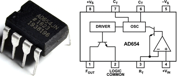
AD654 is a voltage to frequency converter IC and comes in an 8-pin DIP package. It is made out of an input amplifier, a very precise built-in oscillator and a high current open collector output driver which allows the IC to drive up to 12 TTL loads, optocouplers, long cables, or similar loads, and can be operated in between (5-30) Volts. Another thing to mention is that, unlike other IC’s, AD654 IC outputs a square wave, so it's easy for a microcontroller to measure the readings. Some of the most interesting features of this chip listed below.
Features:
- Wide Input Voltage ± 30 V
- Full-scale frequency up to 500 kHz
- High Input Impedance of 125MΩ,
- Low drift (4 µV/°C)
- 2.0 mA Quiescent Current
- Low offset 1 mV
- A minimal requirement for external components
Components Required
| Sl.No | Parts | Type | Quantity |
| 1 | AD654 | IC | 1 |
| 2 | LM7805 | Voltage Regulator IC | 1 |
| 3 | 1000pF | Capacitor | 1 |
| 4 | 0.1uF | Capacitor | 1 |
| 5 | 470uF,25V | Capacitor | 1 |
| 6 | 10K,1% | Resistor | 4 |
| 7 | Potentiometer, 10K | Variable Resistor | 1 |
| 8 | Power Supply Unit | 12V, DC | 1 |
| 9 | Single Gauge Wire | Generic | 6 |
| 10 | Breadboard | Generic | 1 |
Schematic Diagram
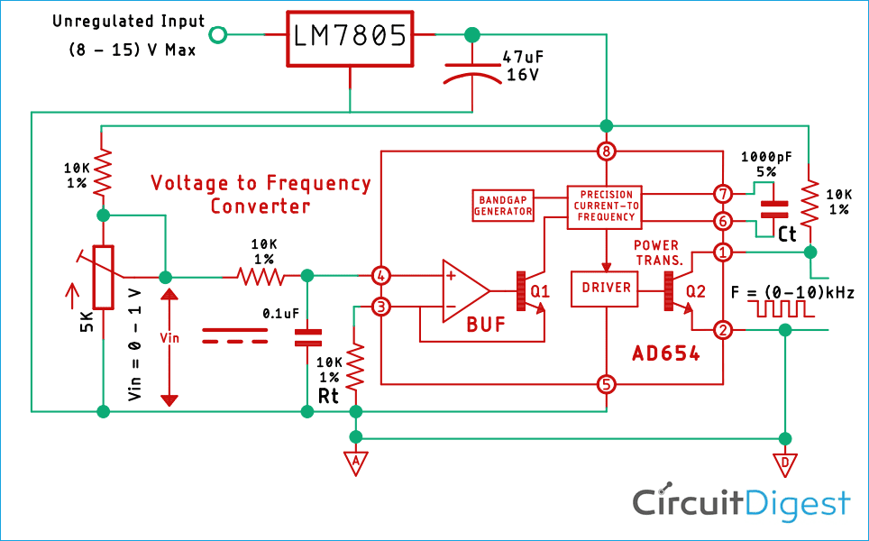
The schematic for this Voltage to Frequency converter circuit is taken from the datasheet and some external components were added to modify the circuit for this demonstration
This circuit is constructed on a solderless breadboard with the components shown in the schematic, for demonstration purposes a potentiometer is added in the input section of the amplifier to vary the input voltage and with that, we can observe the change in output.
Note! All the components are placed as closely as possible to reduce parasitic capacitance inductance and resistance.
How the Device Functions?
The internal operational amplifier is used as the input, and it's there to convert the input voltage to drive current for the NPN follower when a 1mA drive current is provided to the current to a frequency converter. It charges the external timing capacitor and this scheme allows the oscillator to provide nonlinearity over the total voltage range of 100 nA to 2mA. This output also goes to an output driver which is just an NPN power transistor with an open collector from which we can get the output
Calculations
To calculate the output frequency of the circuit theoretically, the following formula can be used
Fout = Vin / 10*Rt*Ct
Where,
- Fout is the output frequency
- Vin is the input voltage of the circuit,
- Rt is the resistor for the RC oscillator
- Ct is the capacitor for the Rc oscillator
For example,
- Vin be 0.1V or 100mV
- Rt is 10000K or 10K
- Ct be 0.001uF or 1000pF
Fout = 0.1 / (10 * 10 * 0.001)

Fout = 1 KHz
So, if 0.1V is applied to the input of the circuit we will get 1kHz in the output
Voltage to Frequency Converter Testing
To test the circuit, the following tools are used
- 12V Switch Mode Power Supply (SMPS)
- Meco 108B+ Multimeter
- Hantech 600BE USB PC Oscilloscope
To construct the circuit, 1% Metal Film Resistors are used and the tolerance of the capacitors is not taken into account. The room temperature was 22 degree Celsius during testing
Test Setup
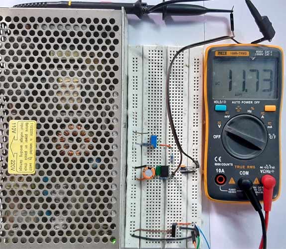
As you can see the DC input voltage is 11.73 V
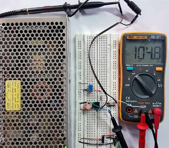
And the voltage at the input pin of the IC is 104.8 mV
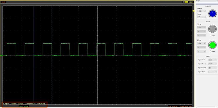
Here you can see the output on my DSO is 1.045 kHz.
A detailed video of the working circuit is given below where multiple inputs were given and the frequency changed in the ratio of the input voltage.
Further Enhancement
By making the circuit on a PCB the stability can be improved, also resistors and capacitors with 0.5% tolerances can be used to improve the accuracy. The most important part of this circuit is the RC oscillator section, so the RC oscillator has to be placed as close as possible to the input pins otherwise, start capacitance and resistance of the PCB traces or the component may reduce the accuracy of the circuit.
Applications
This is a very useful IC and can be used for many applications, some of them listed below
- AD654 VFC as an ADC
- Frequency Doubler
- Temperature sensor with thermocouple
- Strain gauge
- Function Generator
- Self-Biasing Precision Clock
I hope you liked this article and learned something new out of it. If you have any doubt you can ask in the comments below or can use our forums for detailed discussion.

