i have seen jammers to be used in many hollywood movies. I wish i could design one....
So can anyone suggest a better circuit diagram for mobile jammer or signal signal jammer circuit..
i have checked few website and i found the challenging part is to make the inductor, which is hard so i also need the proper specification of the inductor..
Thanks

Most mobile jammer circuit uses a 555 timer IC and a LC oscillator to generate frequency as noise on a particular frequency. The circuit diagram for the same is give below
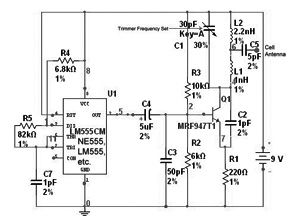
Like all mobile jammer circuits you have to design your own Inductors for this as well, a 2.2nH and 1nH inductor is required. To make an inductor use an enameled (insulation coated) copper wire and make the number of turns required over a BOLT of required diameter and then remove the winding from the bolt to make it look neat.
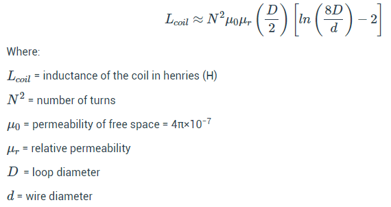
The number of turns depends on the diameter of the Copper wire and diameter of the Bolt. You can use the below formulae to calculate those.
Remember that these circuits are only for educational purpose and is not intended for any harmful purposes.

Aswinth Raj
PermalinkI know that there are a lots of mobile jammer circuits out there, but personally I am not a big fan of these. This is because most of them are illogical and it depends on your luck to get it partially working.
To know why, first you have to understand how mobile phone jammers work. All mobile phones operate at a particular frequency and it is this using which it gets signal from the local station. So to jam a phone we have to disturb the frequency at which it is operating. Say you mobile is operating at 900MHZ then you have to create a circuit that disturbs this 900MHZ frequency by creating dummy waves without signal.
Now the problem is not all mobile phones with 900MHz, in India alone we have 850, 900, 1800, 2100, 2300 MHz and much more. Creating one simple circuit to jam all these signals is not feasible idea. Ofcource you can concentrate on one particular frequency to jam a partcular mobile but gain modern day mobile operators have adapted methods to avoid noisy band and use other frequencies
- Log in or register to post comments
Joined August 16, 2016 998Tuesday at 12:29 AM