Hi I want to build a Zener voltage regulator circuit to convert 12V to 5V for my sensor. The sensor is rated for 5V 20mA. I am trying the below circuit, but I dont know how to calculate the Zener resistance value
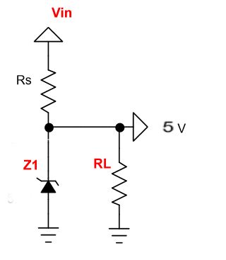
Here Vin is 12V and Z1 is a 5.1V Zener Diode. Can someone please explain the reason why we need Rs and RL. Becasue I powered the circuit without them and even then I got 5.1V across zener. So why I need them and how to calculate the value this two resistors?
Thanks in advance

RS is connected in series with the zener diode to limit the current flow through the diode with the voltage source.Resistor RS is selected so to limit the maximum current flowing in the circuit.The value of the series resistance can be found using the formula below:

where Vs= input voltage
Vz=Zener voltage
Iz=zener current which can found using formula=watt/voltage
RL is the resistive load. It is your circuit that is drawing current from the zener regulator.
The answer is allready given, but i just want to add that the Rs is need to be required.
It is because a zener requires small bias current which is available in the datasheet. The Rs will provide this required current. Therefore choose the Rs by the given calculation before. Without Rs the zener will not became stable in various situations especially in temperature drifts.
This circuit enables a fixed stable voltage to be taken from an unstable voltage source such as the battery bank of a renewable energy system which will fluctuate depending on the state of charge of the bank.
Pictured above is a very simple voltage regulator circuit requiring just one zener diode and one resistor . As long as the input voltage is a few volts more than the desired output voltage, the voltage across the zener diode will be stable.
As the input voltage increases the current through the Zener diode increases but the voltage dropremains constant – a feature of zener diodes. Therefore since the current in the circuit has increased the voltage drop across the resistor increases by an amount equal to the difference between the input voltage and the zener voltage of the diode.
The voltage dropped across the resistor is equal to the difference between the source voltage and the zener voltage = 12-8 = 4 Volts, and therefore the resistance according to Ohm Laws is the voltage drop divided by Imax = 4/0.110 = 36 Ohms so choose a 39 Ohm resisitor.
If the source voltage is likely to be much over the 12 Volts stated then the voltage dropped across the resisitor will be larger and so a resistor with a larger resistance may be required.

Jim
PermalinkRL is not necessary. RS is used to limit the current through the circuit. Z1 is used to dump current to drop voltage. Rs could get hot since you're dropping 7V to get 5.1V. If you don't want to limit current (your 5V load can manage that), do away with both Rs & RL. Make sure Z1 can handle the voltage & current from Vin.
- Log in or register to post comments
Joined November 18, 2019 8Monday at 02:06 AM