This article is the continuation of our tutorial series on programming MSP430 using Code Composer Studio. Last tutorial was based on external interrupts on MSP430 using GPIO pins. This tutorial is about interfacing a display with MSP430, when it comes to display the 16*2 LCD Display, it is the first choice for any electronic hobbyist. Previously we have also interfaced LCD with MSP430 using Arduino IDE, in this tutorial, we will use the native Code Composer studio platform instead of using the Arduino IDE, this way as a designer, we get more flexibility.
To learn more about 16x2 LCD display and using it with other microcontrollers, please see below tutorials.
- Interfacing LCD with ATmega16
- Interfacing LCD with Raspberry Pi
- Interfacing LCD with PIC Microcontroller
- Interfacing LCD with ARM7-LPC2148
- Interfacing LCD with NodeMCU
- Interfacing LCD with STM32
- Interfacing LCD with MSP430G2
- Interfacing LCD with STM8
It has an in-built IC hd44780 that can store the command and data passed to it. The LCD Module has about 16 pins. 8 of which are data pins, 4 of them are supply pins for backlight LED and the whole LCD module, 3 for controlling the operation, and 1 pin for contrast adjustment. The tutorial is based on the library created by Dennis Eichmann. It is very easy to use a library with separate functions to print different data types. It also has provisions to display the data in different forms with leading, blanked, and deleted zeroes. It is a pretty expansive and comprehensive library and is configurable to the different connections. Here, the header file is modified to accommodate an 8-pin parallel configuration for data communication.
16x2 Alphanumeric LCD Display
A generic 16x2 Display has an inbuilt hd44780 IC (circled in red below), that can store the command and data passed to it. The LCD Module has about 16 pins. 8 of which are data pins, 4 of them are supply pins for backlight LED and the whole LCD module, 3 for controlling the operation, and 1 pin for contrast adjustment.
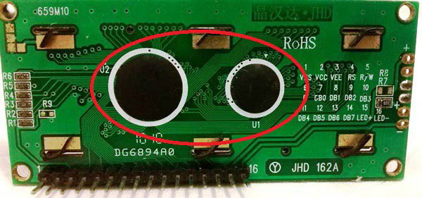
This LCD module is shown above versatile and uses minimum pins compared to other segmented LCDs. If you are curious to know how exactly all this works, you should check out the working of the 16x2 LCD display where we have already discussed how the LCD works in detail.
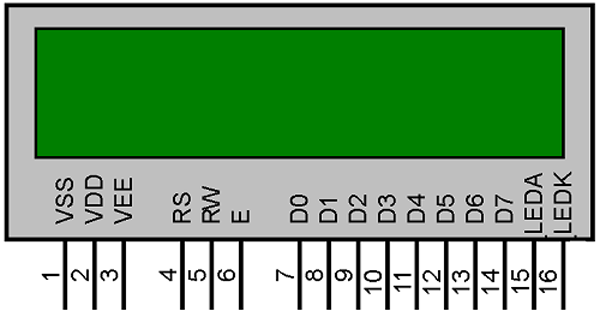
RS Pin: RS=1 will enable the data register in the LCD, which is used to write the values to the data register in LCD. RS=0 will enable the Instruction register of the LCD.
Enable pin: Negative edge-triggered; when the pin is changed from the HIGH state to LOW state, LCD is prompted to write to the data pins. Positive edge-triggered; when the pin is changed from the LOW state to HIGH state, LCD is prompted to read from the data pins.
R/W pin: R/W = 0 will write to the instruction register or data register as per the selection of RS pin. R/W = 1 will read from the IR or DR as per the selection of RS pin.
RS R/W Operation
0 0 IR write as an internal operation (display clear, etc.)
0 1 Read busy flag (DB7) and address counter (DB0 to DB6)
1 0 DR write as an internal operation (DR to DDRAM or CGRAM)
1 1 DR read as an internal operation (DDRAM or CGRAM to DR)
D0-D7 pins: The data is transferred to and from the command and data registers through these pins.
Supply pins: Vss, Vdd pins are used to power the LCD Module. A, K pins will power the LED backlight. V0 pins are used to control the contrast.
16x2 LCD CCS Library for MSP430
The tutorial is based on the library created by Dennis Eichmann. It is very easy to use a library with separate functions to print different data types. It also has provisions to display the data in different forms with leading, blanked, and deleted zeroes. It is a pretty expansive and comprehensive library and is configurable to the different connections. Here, the header file is modified to accommodate an 8-pin parallel configuration for data communication. The library can be download from the below link, after downloading you follow the below steps to add the library to CCS.
Download 16x2 Library for MSP430 – Code Composer Studio
Step 1: Creating Files and Projects
A default CCS project is created using the file menu. In the Create Project dialog box, select the device and give hd44780 as a project name. Under the Project type and toolchain, select the output type as a Static library and create the project.
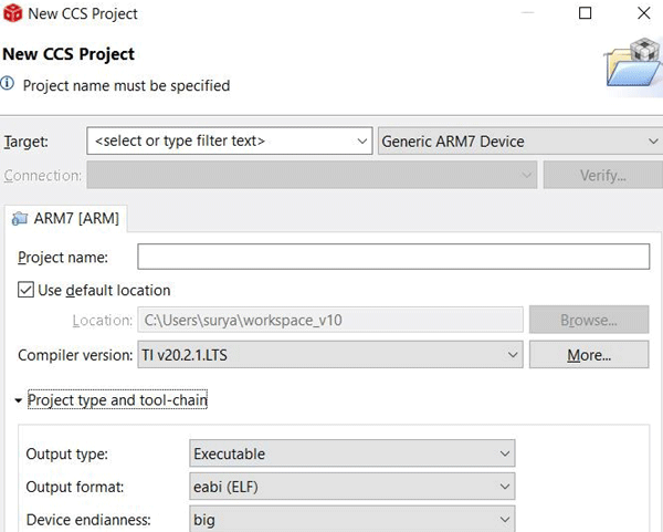
In the Project Explorer lane (left side), create a header file within the include folder and name it as hd44780.h. Then copy the contents of the downloaded hd44780.h file into this newly created one.
Now create the main project by changing the output type to an executable and create a project named CCS_LCD.
Step 2: Include the Search Paths to the Main Project
In the properties dialog box of the hd44780 project and inside the include options for the MSP430 compiler, add the include folder in file the search path.
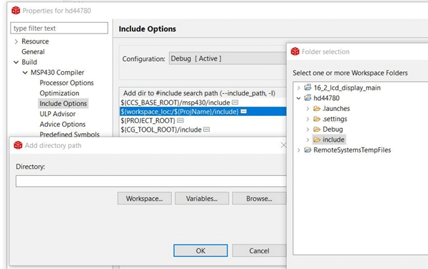
Then, build this project to create the necessary linker files such as .lib files. Building this will create hd44780.lib file inside the debug folder.
Step 3: Include the Search Paths for Linker
In the properties dialog box for the CCS_LCD project and in the file search path of MSP430 Linker tab, include the hd44780.lib located inside the debug folder of the hd44780 project. The debug folder is also included in the file search path.
The include folder is again added to the include options of the MSP430 compiler of the CCS_LCD project.
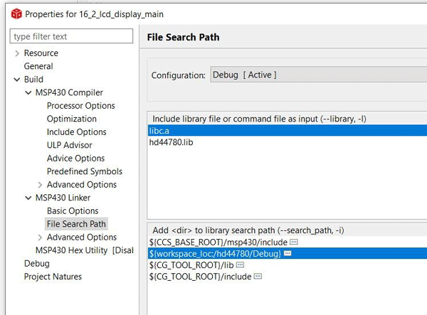
The library is successfully compiled and added to the linker of the main project.
LCD Functions for 16x2 LCD Display on MSP430
void hd44780_timer_isr( void ): This is periodically called in the ISR of the Timer A. The Timer A is used to periodically do the LCD functions like clearing the screen, setting the cursor, and displaying the data. The function is to be used in the ISR. It returns nothing.
uint8_t hd44780_write_string ( char * ch__string, uint8_t u8__row, uint8_t u8__column, uint8_t u8__cr_lf ): It will write the string specified in the first argument.
char * ch__string: The string to be written to the data buffer (inside the hd44780_timer_isr function). The data will be copied to the data register and instruction register of the LCD IC when the hd44780_timer_isr is periodically called.
uint8_t u8__row: It defines the row in which the string will be written.
uint8_t u8__column: It defines the column in which the string will be written.
uint8_t u8__cr_lf: If it is set 1, the row will be carried on to the next one. If it is 0, printing stops at the same row.
void hd44780_clear_screen( void ): This function will clear the whole screen. It returns nothing.
uint8_t hd44780_output_unsigned_16bit_value( uint16_t u16__value, uint8_t u8__leading_zero_handling, uint8_t u8__row, uint8_t u8__column, uint8_t u8__cr_lf ): The function will display the unsigned 16-bit value on the desired location of the LCD.
uint16_t u16__value: The integer to be displayed is given in the first argument.
uint8_t u8__leading_zero_handling: If 0 is passed, leading zeroes will be shown to the integer value will be shown. If 1 is passed, the zeroes will be blanked out. If 2 is passed as a parameter, only the significant digits will be shown.
uint8_t u8__row: The row in which the integer is displayed is selected.
uint8_t u8__column: The column to be printed is selected using the argument.
uint8_t u8__cr_lf: If it is set 1, the row will be carried on to the next one. If it is 0, printing stops at the same row.
Circuit Diagram to Interface LCD with MSP430
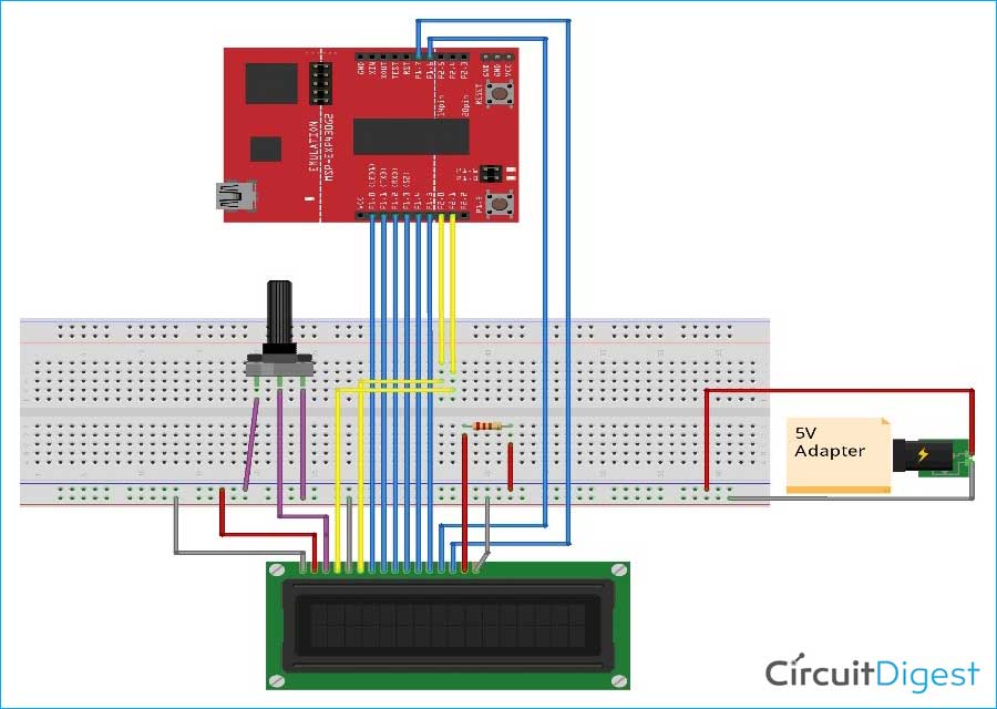
The complete circuit diagram is illustrated in the below image. As you can see, the hardware connections are very simple and we have powered the complete board by using a 5V adapter.
The connections are made as per the above sketch. Please look into the below table for the detailed connections.
| Vss | Ground of 5V Power Supply |
| Vdd | 5V |
| V0 | Potentiometer Output |
| RS | P2.1 |
| R/W | Ground |
| E | P2.0 |
| D0 | P1.0 |
| D1 | P1.1 |
| D2 | P1.2 |
| D3 | P1.3 |
| D4 | P1.4 |
| D5 | P1.5 |
| D6 | P1.6 |
| D7 | P1.7 |
| A | 220 Ohm Resistor |
| K | Ground |
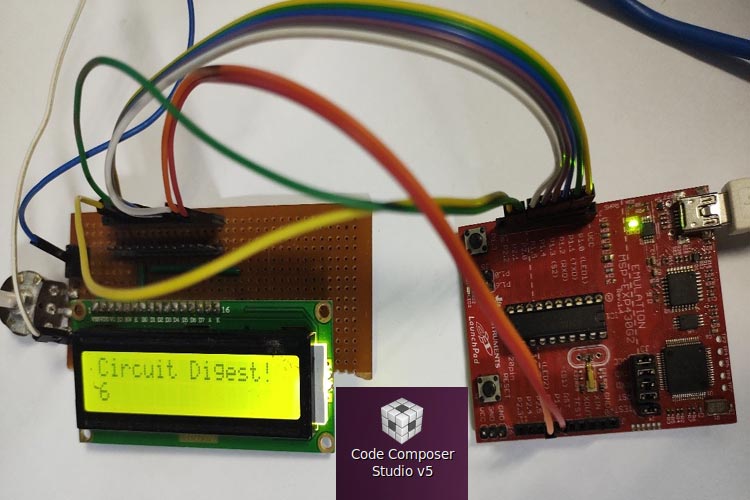
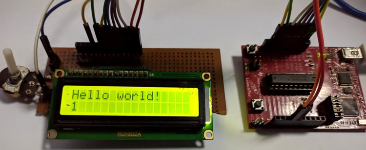
The anode of the LED backlight cannot be connected directly to a 5V supply. It should be connected to a resistance to minimize the current flow through the LCD Module. I have made my connections using a perf board to solder the LCD and then used jumper wires to connect the LCD with the MSP430 board, my set-up looks like this below but you can also simply use a breadboard to make your connections.
Programming MSP430 using Code Composer Studio for LCD Display
The complete code used in this project is given at the bottom of this page. The explanation of using the code is as follows. First, open the header file (hd44780.h) and include the microcontroller part number in the first part of the file.
#include "msp430g2553.h"
The watchdog timer has to be stopped first. DCOCTL and BCSCTL1 control registers are used to configure the oscillator of the microcontroller. The lines below will configure the MCLK to be 1MHZ.
  WDTCTL = (WDTPW | WDTHOLD);
  BCSCTL1 = CALBC1_1MHZ;
  DCOCTL  = CALDCO_1MHZ;
The port 1 pins has to be mentioned as output, which is to be used for the data pins. The pin 0 and pin 1 also has to be mentioned as output in the port 2, which will be used for RS and R/W pin.
P1DIR = 0xFF;
P2DIR = (0x01 | 0x02);
Inbuilt timer is being used to display values periodically. Timer A is selected with SMCLK (1MHZ) as the clock source and continuous mode being the mode of operation.
TA0CCR1  = 32768;
TA0CCTL1 = CCIE;
TA0CTL   = (TASSEL_2 | MC_2 | TACLR);
The interrupts for the compare channels 1 and 2 and timer overflow interrupt share the same interrupt vector (TIMER0_A1_VECTOR) with different starting addresses. Capture compare channel 1 (CCR1) uses 2 as the address, which is being used in the switch case.
#pragma vector = TIMER0_A1_VECTOR
__interrupt void timer_0_a1_isr( void )
{
  switch( TA0IV )
  {
    case 2:
    {
    hd44780_timer_isr();
   break;
   }
 }
}
Once you have your code compiled, you can upload it to the MSP430 board, as explained in the getting started with the MSP430 tutorial. If everything goes as expected, you should see your LCD display some contrast as shown below.
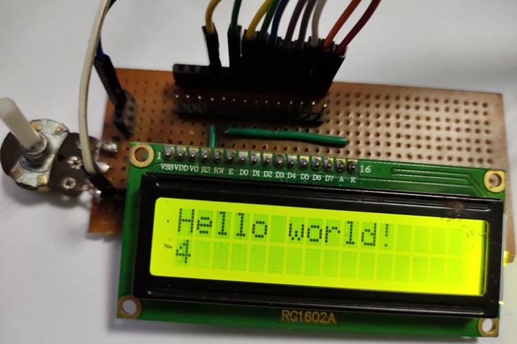
If your test is very dim, you can try adjusting the potentiometer to get better contrast. The complete working of the project can also be found in the video linked below. Hope you enjoyed the project and found it interesting to build your own. If you have any questions, please leave them in the comment section below. You can also write all your technical questions on forums to get them answered or to start a discussion.
#include "msp430g2553.h"           // Microcontroller specific header file
#include "hd44780.h"                    // HD44780 library
uint8_t value=0;
void main( void )
{
WDTCTL = (WDTPW | WDTHOLD);                    // Stop watchdog timer
BCSCTL1 = CALBC1_1MHZ;                              // Set range to calibrated 1MHz
DCOCTL  = CALDCO_1MHZ;             // Set DCO step and modulation for 1MHz
P1DIR = 0xFF;                                    // Set P1.0 (D0) to P1.7 (D7)
P2DIR = (0x01 | 0x02);                      // Set P2.0 (E) and P2.1 (RS) to output
  TA0CCR1  = 32768;                                 // Set CCR1 value for 32.678 ms interrupt
  TA0CCTL1 = CCIE;                                  // Compare interrupt enable
  TA0CTL   = (TASSEL_2 | MC_2 | TACLR);  //SMCLK, Continuous mode
  __bis_SR_register( GIE );                            // Enable global interrupts
  hd44780_clear_screen();                             // Clear display content
  while( 1 )                                                       // Endless loop - main program
  {
    hd44780_write_string( "Circuit Digest!", 1, 1, NO_CR_LF );
    hd44780_output_unsigned_16bit_value( value++, 2, 2, 1, 0 );
    if(value>10)
    value=0;
  }
}
// Directive for timer interrupt
#pragma vector = TIMER0_A1_VECTOR
__interrupt void timer_0_a1_isr( void )                     // Timer 0 A1 interrupt service
{
  switch( TA0IV )                                                        // Determine interrupt source
  {
    case 2:                                                                   // CCR1 caused the interrupt
    {
      hd44780_timer_isr();                                          // Call HD44780 state machine
      break;                                                                        // CCR1 interrupt handling done
    }
  }
}
