Hello electronics makers, this tutorial is going to be very exciting for you because at the end of this tutorial you will be able to program a new super low-cost microcontroller. I am always being curious to try new kinds of development boards and microcontrollers. If you are a regular reader of our website, then you might have seen our previous tutorial series on the STM8S103F3P6 development board. Now we are going to try another microcontroller IC from the STM8 family namely the STM8S001J3. Recently the price surge in semiconductor components has drastically increased the demand and cost of all popular microcontrollers. So there is a good chance many of us are looking for cheaper alternatives, at least I was and I found the STM8S001J3 Microcontroller to be a good choice. But this microcontroller comes in an SMD-SO8N package. So, we need to make a PCB for this IC. At first, we are going to design and manufacture our custom PCB to mount the STM8S001J3 IC and then we will see how to program the STM8S001J3 IC. Let’s know about the STM8S001J3 IC before design the PCB for it.
STM8S001J3 Microcontroller IC
The STM8S001J3 is an 8-bit microcontroller that comes with a good performance, robustness, and at a very cheap cost. It has 8Kbytes of Flash program memory, 16MHz Clock Frequency, 5 Multi-purpose GPIO pins, 3 ADC channels, SPI, I2C, and UART support. You can download the STM8S001J3 user manual for more information. I have marked the STM8S001J3 IC in red color in the image below.
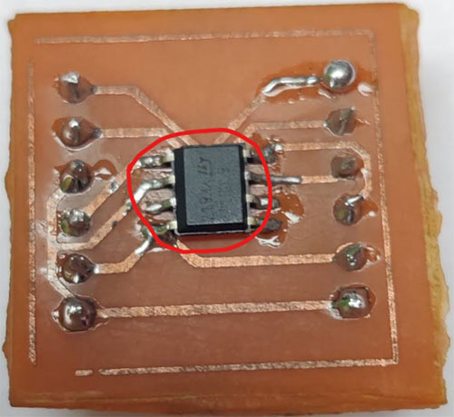
So, we are going to make something similar to the above image. But, if you see the package information section in the datasheet, you will get information about the location of pin number 1 which is important while you are designing a PCB for a SMD component. Honestly, I made this mistake while I was doing it for the first time. As a result, the PCB that I made for the first time, printed wrong and I need to re-manufacture the PCB again by changing the position of the IC. So, I have attached a snapshot of the datasheet below which contains the package information.
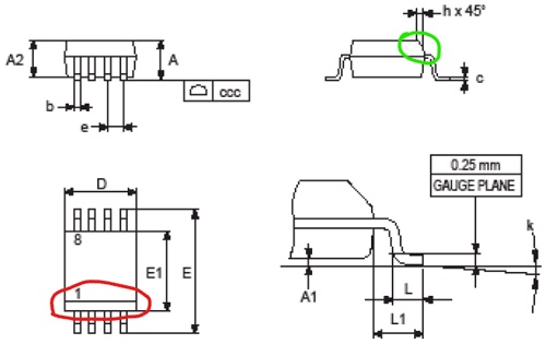
The above image is taken from the datasheet of the STM8S001J3 IC. The areas that I have marked with red and green circles in the image, is representing a slope with an angle of 45 Degree. If you see at the top of the IC, you can find the slope and some texts on the top surface of the IC. The pin number 1 is situated at the same side from where the “ST” text is situated. You can refer to the image below. The slope is marked in Red in the below image. The Pin number 1 is marked in Green color. This information is enough to design the PCB for the STM8S001J3 IC. Now, let’s see the PCB Designing and Manufacturing for the STM8S001J3 IC.
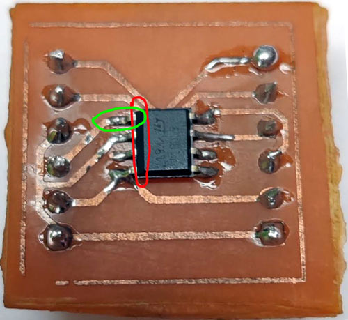
Building and Testing Our Custom PCB for the STM8S001J3
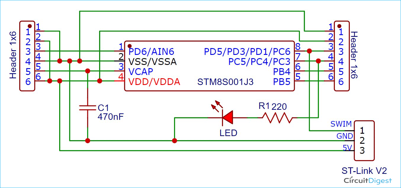
I used the EasyEDA platform to design the schematics and the PCB. The image below shows the schematic where each pin of the STM8S001J3M3TR is connected to the 1x6 pin headers respectively. I have added the VSS pin (Ground Pin) and the VDD pin (5V pin) with 2 extra pins of both pin headers.

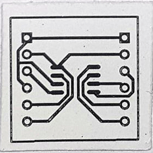
After designing the schematics, we assigned the proper footprints for all the components and arranged the components in the PCB editor tool on the EasyEDA. You can visit the project on EasyEDA to edit the project. The next step is to take a printout of the design in order to etch the PCB. I used an Inkjet printer to take the printout. The below image shows the printout of the PCB on Glossy Paper.
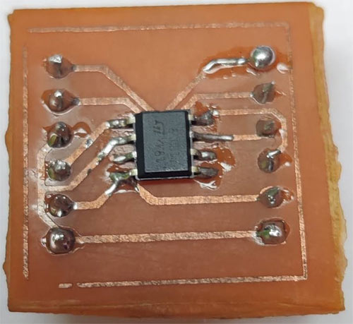
The print is transferred to the copper plate by using a Hot Iron. Then we need to follow the PCB fabrication steps. We have covered many topics related to the PCB Fabrication process on our website that you can check out if you are new to PCB fabrication. When you will complete the fabrication process and soldered the IC and the male pin headers on the PCB, you should have the complete PCB in your hand like the below image shows.
Pin Description of the STM8S001J3
Let’s understand the pin descriptions of the STM8S001J3 microcontroller. The below image is a snapshot of the datasheet of STM8S001J3 IC. As you can see that we have 8 pins in the STM8S001J3 IC. The pin numbers 1,5,6,7 and 8 are the respective multipurpose GPIOs and the pin numbers 2,3 and 4 are the power pins. Pin 2 is used as a Ground pin and pin 4 is used to provide the 5V power supply. Every GPIOs contains multiple communication methods. For example, pin 1 can be used as an ADC input channel, UART-Receiver pin, PORTD6, and PORTA1.
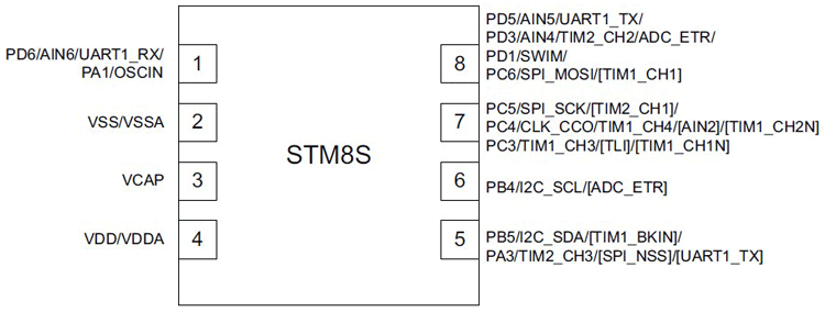
The most important thing is pin 3 and pin 8 is that when you are giving power to the IC, make sure that you have attached a small amount of capacitor to pin number 3 (i.e. VCAP) and pin number 2 (i.e. VSS/VSSA or Ground). It is clearly mentioned in the datasheet that if you are switching the functionality of pin number 8, then you must provide 5 minutes of delay while using the pin 8 as a SWIM pin. Please read the page 9, 10 and 11 of the datasheet that I have provided above.
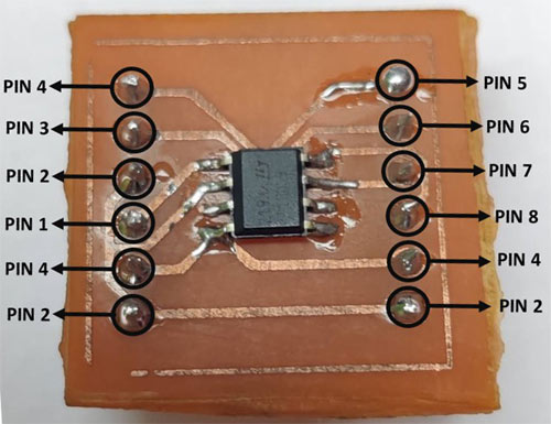
Pin description of our custom PCB for the STM8S001J3 IC
In the following image, I have mentioned the pin description of our custom PCB. As you can see that the PCB has 3 pins to give a 5V power supply and 3 pins to be used as Ground respectively. We can easily mount this PCB on the breadboard and we can program this.
Components Required to Blink an LED with the STM8S001J3 IC
Make sure that you have the following components to program the STM8S001J3 IC. I have used a capacitor of 470nF but you can use a 1uF capacitor or any other capacitor having a small value of capacitance.
- ST-Link V2 Programmer Stick
- LED
- Resistor - 220ohm
- Capacitor – 470nF
Connection Diagram to blink an LED with STM8S001J3
I used the pin number 7 as GPIO that is PC3 (or, you can say PIN3 of PORTC) and connected the Anode pin of the LED to it through a 220K ohm resistor. And the Cathode is connected to the Pin number 2 (i.e. the ground pin of the STM8S001J3 IC). Then we need to connect the SWIM pin, 5V VDD pin, and the Ground pin of the STM8S001J3 IC to the ST-Link V2 Programmer Stick. Add the small amount of Capacitor in between the Pin number 3 (i.e. VCAP pin) and the Ground. This is important to add a capacitor to the pin number 3 because the VCAP pin is attached to the output of an internal voltage regulator of 1.8 volts inside the STM8S001J3 IC.
Install the required software and Download the Standard Peripheral Library for STM8S001J3:
Before starting the programing part make sure that you have gone through with our Getting Started with STM8S using STVD and Cosmic C Compiler tutorial. There you can find how to install and setup the Cosmic C compiler, STVD, and ST Visual Programmer. After you have done the installation part you need to download the Standard Peripheral Library for STM8S001J3 library from our GitHub Repository. The SPL library is distributed by the STMicroelectronics itself. They have provided such a detailed manual for the SPL library which can be used for all 8-bit STM8S/A Microcontrollers. Make sure that you have the SPL Library and the Manual with you before programing any STM8S/A microcontroller.
Compiling the First Program on the STM8S001J3 to Blink an LED
Now that everything is ready, let’s try compiling our first program to check if the IDE, Compiler, and Library are all working the way they should. You can also check the video at the bottom of the page for detailed instructions.
Start by opening STVD and select “File -> New Workspace” as marked in red on the below image.
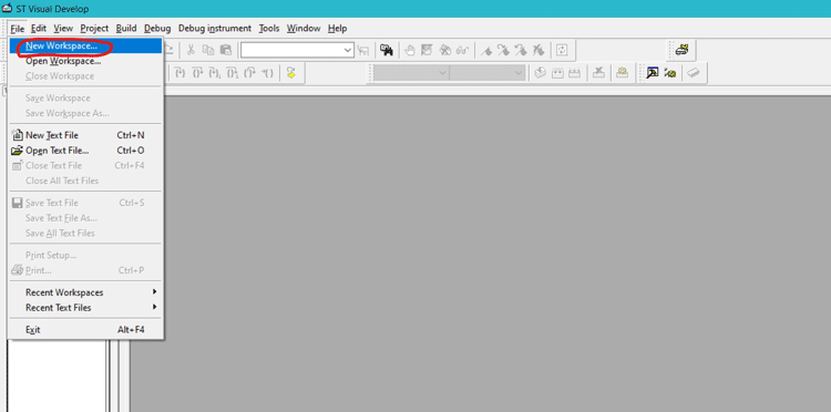
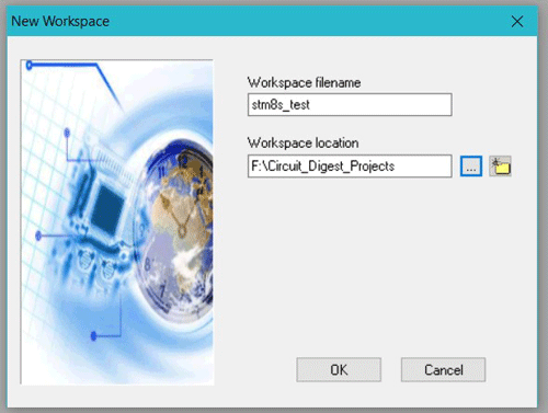
Then you will get a new pop-up similar to the below image. Select the “Create workspace and project” and click on “OK”.

Then you need to give the Project name and path where the workspace should be saved. I am naming my workspace as “stm8s_test1” and saving it in a folder. You can refer to the following image below.
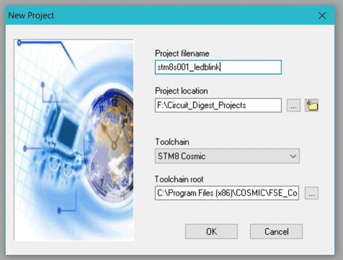
Then you need to give the project filename. And select the “Toolchain” as Cosmic C compiler from the dropdown as shown in the image below. If you have already installed the Cosmic C Compiler on your desktop, then you need to provide the location of the installed file of the Cosmic C compiler for the first time. Make sure that you have installed the Cosmic C compiler with the free License as mentioned in our Getting started with the STM8S103F3P6 tutorial.
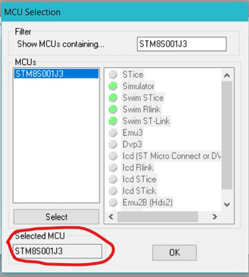
When you click on the OK button, you will get another pop-up named “MCU Selection”. Enter the “STM8S001J3” in the Filter box that can be found in the top right corner of the pop-up window. Then select the “STM8S001J3” in the “MCUs” box. When you have selected the “STM8S001J3”, it will get displayed in the “Selected MCU” section as shown in the image below. Then click on “OK”.
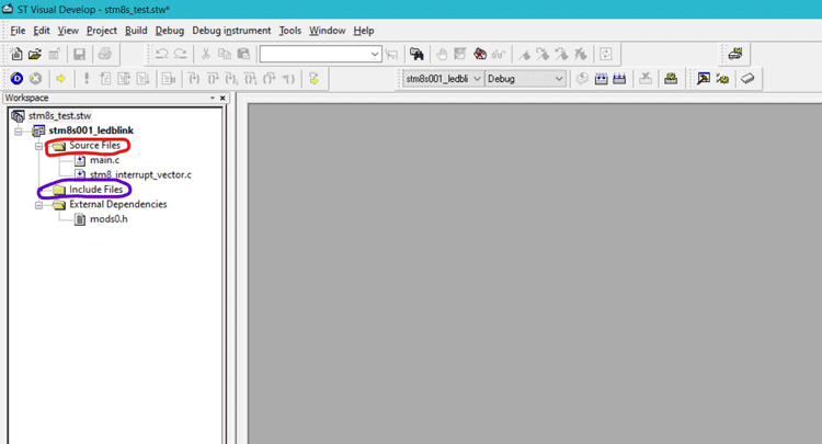
So, we have created a new workspace for our program. Now, let’s try to figure out the file structure first. As you can see in the image below, we have the two important subfolders under the project file that I have marked in different colors. The “Source Files” can be used to add the required C files of the project and the “Include Files” is used to store the required header file of the project. You can include the required C and header files by right click on the “Source Files” and “Include Files” respectively.
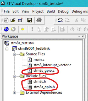
Now, download the required files for the project from our GitHub repository. When you have downloaded the code files, you will have two subfolders named “src” and “inc” under the “T1_Getting Started_with_the_STM8S001J3” folder. You can add the source files and include files as per your project’s requirements. For the led blinking project, we need the following files as you can see in the image below. I have marked the required source files and include files in red.
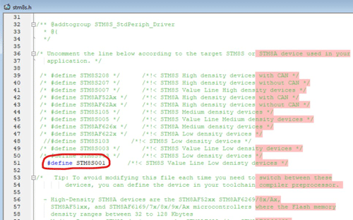
The “stm8s.h” file contains all specifications of all versions of the STM8S Microcontrollers. We need to uncomment the “STM8S001” that can be found in the “stm8s.h” file. You can refer to the image below.
Now, you can copy the below code to blink an LED with the STM8S001J3 in the main.c file. We need to include the “stm8s.h” header file at the top of the code. Then I have defined the “GPIOC” as “PORT1_GP” and “GPIO_PIN_3” as “PINC3”. Please be careful while using the GPIOs. Do not use the pin 8 of the IC as GPIO until you are providing 5 seconds of delay otherwise it will lock the pin 8 and you will not able to upload any program in the future. For more information, read “Section 7.2” of the documentation.
#include "stm8s.h"
#define PORT1_GP (GPIOC)
#define PINC3 (GPIO_PIN_3)
The delay function is used to provide the delay in milliseconds. We have two for loop iterating the _asm("nop") function for the given “ms” of delay. The _asm(“nop”) can be used to instruct the microcontroller not to perform any operation.
void delay (int ms) //Function Definition
{
int i =0 ;
int j=0;
for (i=0; i<=ms; i++)
{
for (j=0; j<120; j++) // Nop = Fosc/4
_asm("nop"); //Perform no operation //assembly code
}
}
Inside the main() function I initialized the pin number 8 as only the PIN3 of the PORTC. Then in the while loop, I used the GPIO_WriteReverse() and delay() functions to toggle the LED with the delay of 500 milliseconds respectively.
main()
{
                GPIO_Init(PORT1_GP, (GPIO_Pin_TypeDef)PINC3, GPIO_MODE_OUT_PP_LOW_FAST);
while (1){
GPIO_WriteReverse(PORT1_GP, (GPIO_Pin_TypeDef)PINC3);
delay(500);
}
}
Uploading the Code from STVD to STM8S001J3 Development Board using ST-Link V2
You need to make sure that you have installed the ST Visual Programmer and connect the ST-Link V2 stick to the respective pins of Custom STM8S001J3 PCB as mentioned in the table below.
|
STM8S001J3 PCB |
ST-Link V2 |
|
Pin number 2 |
GND |
|
Pin number 4 |
5V |
|
Pin number 8 |
SWIM |
Make the connection and connect the device to your computer, the driver installation should begin automatically. You can use the device manager to ensure if your computer has discovered ST-LINK V2 correctly. As soon as we have successfully compiled the code on STVD, we will get an “S19” extension file under the debug directory of the project folder. The S19 file is shown below.
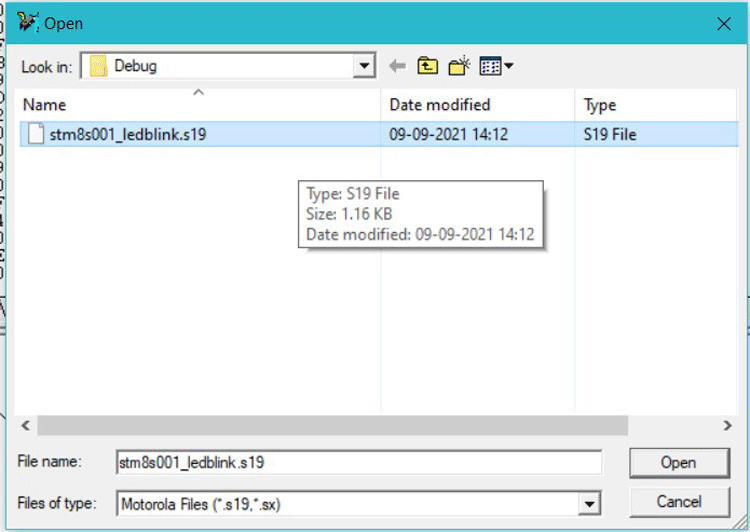
This S19 is like the Hex file which should be uploaded to the controller. To upload the program, open ST Visual Programmer (STVP) which should have been installed along with STVD. Then in the configuration window, select as shown in the below image and click OK.
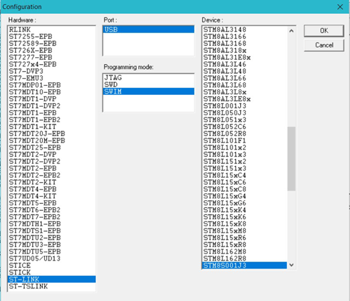
Then click on File->Open and navigate to the S19 file that we showed earlier. Then to flash the device, follow Program -> Current Tab. If the flashing was successful, you should see the following output.

So, we have successfully uploaded the LED blinking program on the STM8S001J3 IC. Now, disconnect and reconnect the ST-Link V2 stick to check the output of the program. Also, check out the video at the bottom for more additional details.
#include "stm8s.h"
#define PORT1_GP (GPIOC)
#define PINC3 (GPIO_PIN_3)
void delay (int ms) //Function Definition
{
int i =0 ;
int j=0;
for (i=0; i<=ms; i++)
{
for (j=0; j<120; j++) // Nop = Fosc/4
_asm("nop"); //Perform no operation //assembly code
}
}
main()
{
	GPIO_Init(PORT1_GP, (GPIO_Pin_TypeDef)PINC3, GPIO_MODE_OUT_PP_LOW_FAST);
while (1){
GPIO_WriteReverse(PORT1_GP, (GPIO_Pin_TypeDef)PINC3);
delay(500);
}
}
