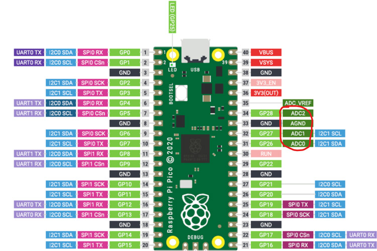
We are here with yet another tutorial of the Raspberry Pi Pico. If you are following our Raspberry Pi Pico tutorial series, then you already know the basic setup and how to interface an OLED display module with the Raspberry Pi Pico. In this tutorial, we will use the Pico board to perform an ADC conversion. The Raspberry Pi Pico has four 12-bit ADC channels, but one of them is connected to the internal temperature sensor. The remaining ADCs are located at GPIO26, GPIO27, and GPIO28 as ADC0, ADC1, and ADC2, respectively. You can see the ADC pins highlighted in red in the image below.

Hardware Required to Perform ADC on Raspberry Pi Pico
We need the following components to perform the ADC on the Raspberry Pi Pico.
- Raspberry Pi Pico
- Potentiometer (10K ohm)
- 1.3 Inch I2C 128x64 OLED Display Module 4 Pin
- Connecting Wires
- breadboard
Schematic Diagram for the ADC on Raspberry Pi Pico Using MicroPython
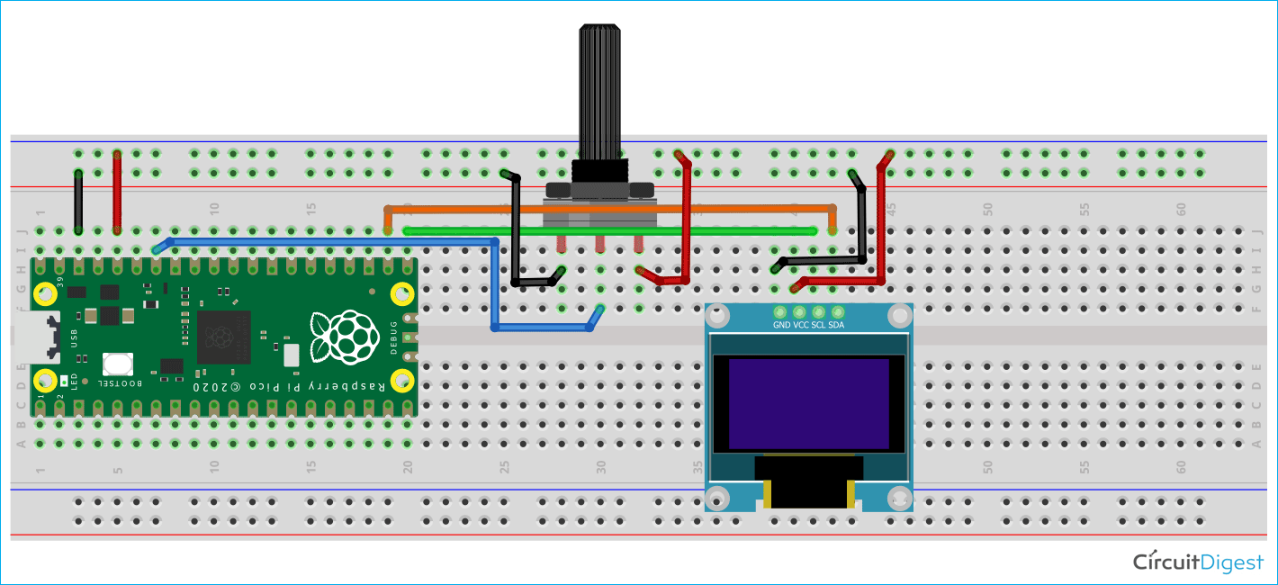
A potentiometer is attached to the Raspberry Pi Pico's 3.3v, GPIO28, and Ground pins in the circuit diagram below. The SDA and SCL pins of the OLED display are linked to GPIO16 and GPIO17, respectively, while the VCC pin of the OLED module is connected to the Pico board's 3.3v pin. The ground pin of the OLED display module is linked to the Ground pin of the Raspberry Pi Pico.
ADC on Raspberry Pi Pico using MicroPython
So, on the Raspberry Pi Pico, we have three ADC channels with a resolution of 12 bits. However, when we program the Pico with MicroPython, we get a 16-bit resolution as a consequence. Actually, in the MicroPython ADC library, they have scaled the 12-bit resolution into a 16-bit resolution, which is why we will receive a maximum ADC value of 65535 (i.e. 2^16) rather than 4096 (i.e. 2^12). Because we have connected the Potentiometer's output pin to the GPIO28 or ADC2, we will use the ADC2 channel and convert the ADC's resulting value between 0V and 3.3V. To obtain the voltage value, we shall multiply a conversion factor by the resulting ADC value.
Before getting started with the coding part, download the GitHub repository. Then open the “T3_ADC_on_Pico” folder. You will find two sub-folders named as “codes” and “images”. In the code folder, we have two files i.e. “main.py” and “ssd1306.py”. We have already discussed about the “ssd1306.py” in our previous tutorial on how to interface an OLED display module with pico. Now, let’s focus on the “main.py” file below.
Programming the Raspberry Pi Pico using MicroPython to display the ADC value on OLED display
Let’s see the MicroPython programming on the Raspberry Pi Pico. In the “main.py” file, we have the “machine.py” library and the “ssd1306.py” library. The machine library is a built-in MicroPython library which has the functions for the basic operations like I2C, ADC, SPI, etc. We will be using 3 important classes like Pin, ADC, I2C. The ssd1306.py library is used for the OLED display. We have already discussed about this library in our previous tutorial on how to interface the OLED display module with the Raspberry Pi Pico. The utime.py library is used to give time delays in the program.
from machine import Pin, I2C, ADC
from ssd1306 import SSD1306_I2C
import utime
The machine.ADC(28) is used to define the ADC channel that is GPIO28. The conversion_factor variable will be used to calculate the actual voltage by multiplying this with the resultant ADC value. Then we have the I2C(0, scl=Pin(17), sda=Pin(16), freq=200000) that is used to initialize an I2C communication as we have discussed in the interfacing of the OLED display with the pico tutorial. The “SSD1306_I2C()” function is used to create the “oled” object which can be used to perform the operations on OLED display.
analog_value = machine.ADC(28)
conversion_factor = 3.3 / (65535)
WIDTH  = 128       # oled display width
HEIGHT = 64         # oled display height
i2c = I2C(0, scl=Pin(17), sda=Pin(16), freq=200000)       # Init I2C using pins GP8 & GP9 (default I2C0 pins)
oled = SSD1306_I2C(WIDTH, HEIGHT, i2c)              # Init oled display
In the below code, the OLED display screen will be cleared by using the oled.fill(0) function. Then we are displaying some text with their corresponding position by using the oled.text() function. The oled.show() function will display those texts on the OLEDdisplay.
# Clear the oled display in case it has junk on it.
oled.fill(0)
# Add some text
oled.text("CIRCUIT",5,8)
oled.text("DIGEST",45,18)
oled.text("ADC",28,40)
# Finally update the oled display so the image & text is displayed
oled.show()
utime.sleep(1)
In the while loop below, we read the ADC at GPIO28 using the analog_value.read_u16() function and store it in the reading variable. However, as we previously discussed, this adc value is in 16-bit resolution because the read_u16() function in MicroPython returns a 16-bit resolution value. So we multiply the conversion_factor by the reading variable to map this 16-bit ADC value into the range of 0V to 3.3V. The voltageValue is then displayed by using the oled.text() function.
while True:
    oled.fill(0)
    reading = analog_value.read_u16()
    print("ADC: ",reading)
    utime.sleep(0.2)
    voltageValue = reading* conversion_factor
    oled.text("Voltage:",5,8)
    oled.text(str(voltageValue)+"V",15,25)
    oled.show()
    utime.sleep(1)
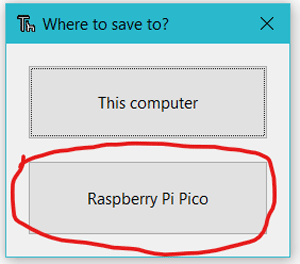
Now, in the Thonny IDE, open the “main.py” and “ssd1306.py” files. To begin, save the “ssd1306.py” file on the Pico board by pressing the “ctrl+shift+s” keys on your keyboard. Before saving the files, make sure your Pico board is connected to your laptop. When you save the code, a popup window will appear, as shown in the image below. You must first select the Raspberry Pi Pico, then name the file “ssd1306.py” and save it. Then repeat the process for the “main.py” file. This procedure enables you to run the program when the Pico is turned on.

In the following video, you can see that when the value of the potentiometer is changing, the voltage level also varyies from 0V to 3.3V. If you have any doubt regarding the programming part, then you can watch the video below because it has a detailed explanation on how to perform an ADC on Raspberry Pi Pico.
# Display Image & text on I2C driven ssd1306 OLED display
from machine import Pin, I2C, ADC
from ssd1306 import SSD1306_I2C
import utime
analog_value = machine.ADC(28)
conversion_factor = 3.3 / (65535)
WIDTH = 128 # oled display width
HEIGHT = 64 # oled display height
i2c = I2C(0, scl=Pin(17), sda=Pin(16), freq=200000) # Init I2C using pins GP8 & GP9 (default I2C0 pins)
print("I2C Address : "+hex(i2c.scan()[0]).upper()) # Display device address
print("I2C Configuration: "+str(i2c)) # Display I2C config
oled = SSD1306_I2C(WIDTH, HEIGHT, i2c) # Init oled display
# Clear the oled display in case it has junk on it.
oled.fill(0)
# Add some text
oled.text("CIRCUIT",5,8)
oled.text("DIGEST",45,18)
oled.text("ADC",28,40)
# Finally update the oled display so the image & text is displayed
oled.show()
utime.sleep(1)
while True:
oled.fill(0)
reading = analog_value.read_u16()
print("ADC: ",reading)
utime.sleep(0.2)
voltageValue = reading* conversion_factor
oled.text("Voltage:",5,8)
oled.text(str(voltageValue)+"V",15,25)
oled.show()
utime.sleep(1)


