In one of our previous projects, we interfaced SX1278(Ra-02) based LoRa module with Arduino and established communication among them. This was a very simple project and can come in handy for various applications. But what it can't do is establish communication with the internet for modern-day IoT applications. So in this project, we will be using the HPD13A which is a SX1276 IC-based LoRa module to establish communication with the things network, so we can use this module for IoT-related applications. So without further ado let's get right into it.
HPD13A - SX1276 Based LoRa Module Pinout
The pinout of the HPD13A - SX1276-based LoRa module is shown below. For this tutorial, we will be using the HDP13A V1.1 LoRa Module which is designed and developed by HPDTeK a well-known manufacturer in china. The pinout of the module is shown below.
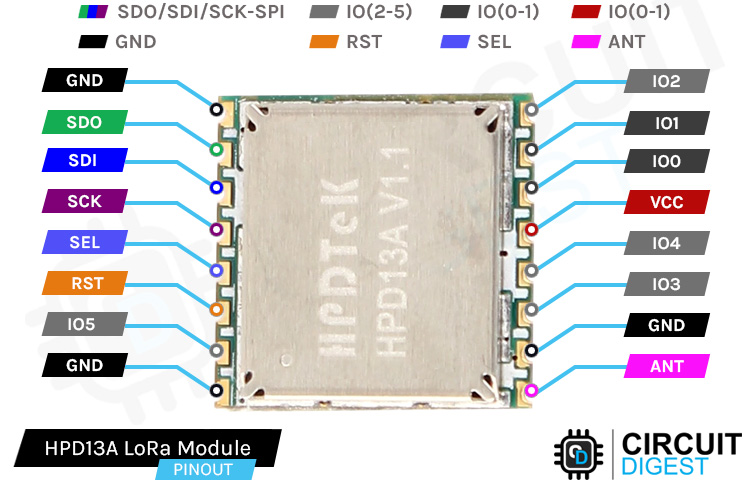
GND This is the Ground Pin of the module that should be connected to the Ground pin of the ESP32 or Arduino whichever microcontroller you are using. There are a total of three ground pins on the board, all those are connected internally.
SDO(MISO) The SDO pin is the Serial Data Out pin of the Microcontroller. An output signal on a device where data is sent out to another SPI device.
SDI(MOSI) The SDI pin is the Serial Data In for the Microcontroller. An input signal on a device where data is received from another SPI device.
SCK It is the Serial Clock Pin of the Module; the Serial Clock is generated by the microcontroller.
SELis the Chip Select pin of the Module. Activated by the controller to initiate communication with a given peripheral.
RSTThis is the Reset pin of the module board which is used to reset the microcontroller to its initial values.
IO(2-5)This is the GPIO pins of the LoRa module. This can be set to High or Low in Software.
ANTThis is the pin where the Antenna needs to be attached. You need to connect a proper antenna according to the datasheet.
VCCThis is the power pin of the module, you can connect this to the VCC pin to any 3.3V. As the max voltage level of the module is 3.3V.
The SX1276 886 MHZ LoRa Module
For this tutorial, we will be using the 868MHZ lora module which is designed and manufactured by SEMTECH. The module is a very easy-to-use, low-cost, high-efficiency module that can be used in many different applications.
The SX1276/77/78/79 transceivers feature the LoRaTM long-range modem that provides ultra-long range spread spectrum communication and high interference immunity whilst minimizing current consumption. It's said that by using SX1276 one can achieve a sensitivity of over -148dBm using a low-cost crystal and bill of materials.
What is the Difference Between HPD13A SX1276 and RFM95W Lora Module
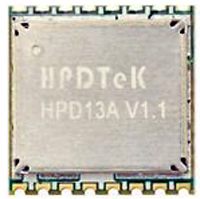
As you can see from the above image, the name of the module is shown as the HPD13A module and the listing on the distributor's website said it was the SX1276 LoRa module. This was very confusing at first.
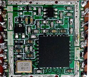
So we decided to decap the model to see what's underneath. And from the above image, you can see we found out that the company named HPDTek assembled the module so they are using their own part number and under the hood, you can see it's made out of the SX1276 LoRa IC.
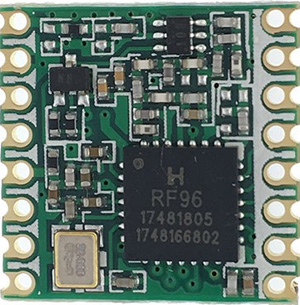
Now the question remains what is the difference between the RFM95W and the HX1276 ic. The modules are the same so the characteristics of the modules are also the same. If your objective is to establish LoRa communication this is not that hard to do. HopeRF licenses the technology from Semtech. So the unshielded RFM95W module is virtually identical to some of the SX127x modules and its pin and software are also compatible. In the above image, you can see the difference between the two modules.
Making Breakout Board with Perfboard
If you check the pin pitch of the module, it's not breadboard friendly so we need to make a breakout board for the module, and there are two ways to do so. You can make a breakout board by soldering the module in a perf board and soldering some header pins to it. The second way is to make a PCB for the model and solder the module to the PCB. For our case, we have selected the first method as it is simple and takes very little time. The complete construction of the breakout board is shown below.

If you check out the HPA13A module it comes with a metal shield cap to reduce EMI and interference. We have removed the cap to see the internal construction of the module as you can see in the above picture. We did this because it will give us a good idea of what is inside the module.
Commonly Asked Questions about LoRa Module
Q. What is LoRa modulation?
LoRa is a wireless modulation technique derived from Chirp Spread Spectrum (CSS) technology. It encodes information on radio waves using chirp pulses - similar to the way dolphins and bats communicate! LoRa modulated transmission is robust against disturbances and can be received across great distances.
Q. How far can LoRa transmit?
The name, LoRa, is a reference to the extremely long-range data links that this technology enables. Created by Semtech to standardize LPWANs, LoRa provides for long-range communications: up to three miles (five kilometers) in urban areas, and up to 10 miles (15 kilometers) or more in rural areas (line of sight).
Q. Is LoRa legal in India?
So in reality a major portion of the 868 MHz LoRa frequency channels are in the license-free 865 MHz – 867 MHz band in India. Seven out of the eight channels are in the license-free band in India.
Q. Can LoRa work without an antenna?
No, the antenna is tuned to a specific range of frequencies, (WiFi is 2.4Ghz or 5Ghz,LoRa is a number of frequencies 166Mhz-915Mhz) using the wrong antenna means it will not be able to pick up (or transmit) signals in the right frequency range.
HPD13A LoRa Module Connection With Arduino
Now that we completely understand how the LoRa Module works; we can connect all the required wires to the Arduino UNO board, and in this section of the article, we will discuss just that!
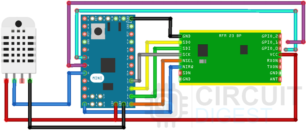
The connection diagram of the SX1276 module with Arduino is shown above, you can see that we have connected the Arduino with the SX1276 module with the SPI pins of the Arduino and we have connected the DHT22 sensor with pin 5 of the Arduino. In this project, we are using an Arduino Pro Mini to interface with the module because the SX1276 module is not 5V tolerant so we are powering the Arduino Pro Mini with 3.3V from USB to Uart Converter.
TTN ABP vs OTAA Activation Methode
Every end device must be registered with a network before sending and receiving messages. This procedure is known as activation. There are two activation methods available:
- Over-The-Air-Activation (OTAA) - the most secure and recommended activation method for end devices. Devices perform a join procedure with the network, during which a dynamic device address is assigned and security keys are negotiated with the device.
- Activation By Personalization (ABP) - requires hardcoding the device address as well as the security keys in the device. ABP is less secure than OTAA and also has the downside that devices can not switch network providers without manually changing keys in the device.
The join procedure for LoRaWAN 1.0.x and 1.1 is slightly different. The following two sections describe the join procedure for LoRaWAN 1.0.x and 1.1 separately.
If you want to learn more about Device Activation Process on TTN you can follow the linked documentation on the TTN website.
Setting up the End Nodes on the TTN Network
To transmit data to the TTN network you need to first set up your gateway and once that is done you need to set up your end nodes properly in order for the device to work properly.
You can check out the step-by-step guide to setting up end nodes on TTN network here.
Arduino Code for Interfacing SX1276 Module with Arduino
The code for interfacing the HPD13A SX1276 Based Lora module is very simple and easy to understand. All we need to do is download the arduino-lmic library by mcci-catena and use its example code to communicate with the SX1276 module. But in this example, we will be doing a little bit extra and sending counter data to the TTN network to see the live data update.
But after you installed the library we need to configure the library to work with the SX1276. For that, we need to go to our default installed library location.
For us it's in C:\Users\USER\Documents\Arduino\libraries\arduino-lmic-master\project_config
And we need to uncomment the CFG_eu868 1 and CFG_sx1276_radio 1 and comment out everything else.
// project-specific definitions
// project-specific definitions
#define CFG_eu868 1
//#define CFG_us915 1
//#define CFG_au915 1
//#define CFG_as923 1
// #define LMIC_COUNTRY_CODE LMIC_COUNTRY_CODE_JP /* for as923-JP; also define CFG_as923 */
//#define CFG_kr920 1
//#define CFG_in866 1
#define CFG_sx1276_radio 1
Next, we will open up the example sketch TTN-OTAA by going to File > Examples > MCCI LoRaWAN LMIC Library > ttn-otaa-feather-us915-dht22 and modify the code a little bit to make it compatible with the SX1276 Module.
Now we need to add in the APPEUI(Application Extended Unique Identifier), DEVEUI(Device Extended Unique Identifier), APPKEY(Application Key). In the code below we just did that.
// This EUI must be in little-endian format, so least-significant-byte
// first. When copying an EUI from ttnctl output, this means to reverse
// the bytes. For TTN issued EUIs the last bytes should be 0xD5, 0xB3,
// 0x70.
static const u1_t PROGMEM APPEUI[8] = { 0x00, 0x00, 0x00, 0x00, 0x00, 0x00, 0x00, 0x00 };
void os_getArtEui (u1_t* buf) {
  memcpy_P(buf, APPEUI, 8);
}
// This should also be in little endian format, see above.
static const u1_t PROGMEM DEVEUI[8] = { 0xFF, 0x43, 0x45, 0xD0, 0xDE, 0xD5, 0xB3, 0x70 };
void os_getDevEui (u1_t* buf) {
  memcpy_P(buf, DEVEUI, 8);
}
static const u1_t PROGMEM APPKEY[16] = { 0xBB, 0xAB, 0xAA, 0xD6, 0x47, 0x5A, 0xAC, 0xBC, 0x36, 0xAC, 0x22, 0x4A, 0xF2, 0x78, 0x33, 0x72 };
Now we need to set up the pins for the module, inside the code you will see a structure that is shown below-
const lmic_pinmap lmic_pins = {
  .nss = 5,
  .rxtx = LMIC_UNUSED_PIN
  .rst = 4,
  .dio = {34, 35, LMIC_UNUSED_PIN},
};
In the structure, you need to assign the NSS. RST, IO0, and IO1 pins, once we do that then the configuration portion is done and now we need to change which pin the DHT sensor is connected to and what DHT sensor we are using.
// DHT digital pin and sensor type
#define DHTPIN 5
#define DHTTYPE DHT22
As shown in the schematic we are using the Arduino pin 5 and we are using a DHT22 sensor. Finally, we need to remove some functions because it's used to set the frequency and transmit power of the module and if we don't do so, then it will present us with errors.
 LMIC_setLinkCheckMode(0);
    // Set the data rate to Spreading Factor 7.  This is the fastest supported rate for 125 kHz channels, and it
    // minimizes air time and battery power. Set the transmission power to 14 dBi (25 mW).
    LMIC_setDrTxpow(DR_SF7,14);
    // in the US, with TTN, it saves join time if we start on subband 1 (channels 8-15). This will
    // get overridden after the join by parameters from the network. If working with other
    // networks or in other regions, this will need to be changed.
    LMIC_selectSubBand(1);
Once this is done, we can compile the code and upload it to the Arduino. If everything works correctly, you can first see the authentication process and then temperature data on the serial monitor window.
Working of the LoRa Module
The gif below shows the working of the LoRa module in action. We have written the code so that when the counter increments, the counter value gets printed on the serial monitor window and we can also see that value that is shown on the TTN webpage.
Supporting Files
/*******************************************************************************
 * The Things Network - Sensor Data Example
 *
 * Example of sending a valid LoRaWAN packet with DHT22 temperature and
 * humidity data to The Things Networ using a Feather M0 LoRa.
 *
 * Learn Guide: https://learn.adafruit.com/the-things-network-for-feather
 *
 * Copyright (c) 2015 Thomas Telkamp and Matthijs Kooijman
 * Copyright (c) 2018 Terry Moore, MCCI
 * Copyright (c) 2018 Brent Rubell, Adafruit Industries
 *
 * Permission is hereby granted, free of charge, to anyone
 * obtaining a copy of this document and accompanying files,
 * to do whatever they want with them without any restriction,
 * including, but not limited to, copying, modification and redistribution.
 * NO WARRANTY OF ANY KIND IS PROVIDED.
 *******************************************************************************/
#include <lmic.h>
#include <hal/hal.h>
#include <SPI.h>

// include the DHT22 Sensor Library
#include "DHT.h"

// DHT digital pin and sensor type
#define DHTPIN 5
#define DHTTYPE DHT22

//
// For normal use, we require that you edit the sketch to replace FILLMEIN
// with values assigned by the TTN console. However, for regression tests,
// we want to be able to compile these scripts. The regression tests define
// COMPILE_REGRESSION_TEST, and in that case we define FILLMEIN to a non-
// working but innocuous value.
//
#ifdef COMPILE_REGRESSION_TEST
#define FILLMEIN 0
#else
#warning "You must replace the values marked FILLMEIN with real values from the TTN control panel!"
#define FILLMEIN (#dont edit this, edit the lines that use FILLMEIN)
#endif


// This EUI must be in little-endian format, so least-significant-byte
// first. When copying an EUI from ttnctl output, this means to reverse
// the bytes. For TTN issued EUIs the last bytes should be 0xD5, 0xB3,
// 0x70.
static const u1_t PROGMEM APPEUI[8] = { 0x00, 0x00, 0x00, 0x00, 0x00, 0x00, 0x00, 0x00 };
void os_getArtEui (u1_t* buf) {
  memcpy_P(buf, APPEUI, 8);
}

// This should also be in little endian format, see above.
static const u1_t PROGMEM DEVEUI[8] = { 0xF5, 0x33, 0x05, 0xD0, 0x7E, 0xD5, 0xB3, 0x70 };
void os_getDevEui (u1_t* buf) {
  memcpy_P(buf, DEVEUI, 8);
}

// This key should be in big endian format (or, since it is not really a
// number but a block of memory, endianness does not really apply). In
// practice, a key taken from ttnctl can be copied as-is.
static const u1_t PROGMEM APPKEY[16] = { 0xB8, 0x2B, 0xEA, 0xC6, 0x49, 0x5A, 0xAC, 0xBC, 0x36, 0xAC, 0x22, 0x4A, 0xF2, 0x78, 0x33, 0x72 };
void os_getDevKey (u1_t* buf) {
  memcpy_P(buf, APPKEY, 16);
}

// payload to send to TTN gateway
static uint8_t payload[5];
static osjob_t sendjob;

// Schedule TX every this many seconds (might become longer due to duty
// cycle limitations).
const unsigned TX_INTERVAL = 30;

// Pin mapping for Adafruit Feather M0 LoRa
// /!\ By default Adafruit Feather M0's pin 6 and DIO1 are not connected.
// Please ensure they are connected.
const lmic_pinmap lmic_pins = {
  .nss = 9,
  .rxtx = LMIC_UNUSED_PIN,
  .rst = 10,
  .dio = {8, 7, LMIC_UNUSED_PIN},
};

// init. DHT
DHT dht(DHTPIN, DHTTYPE);

void printHex2(unsigned v) {
    v &= 0xff;
    if (v < 16)
        Serial.print('0');
    Serial.print(v, HEX);
}

void onEvent (ev_t ev) {
    Serial.print(os_getTime());
    Serial.print(": ");
    switch(ev) {
        case EV_SCAN_TIMEOUT:
            Serial.println(F("EV_SCAN_TIMEOUT"));
            break;
        case EV_BEACON_FOUND:
            Serial.println(F("EV_BEACON_FOUND"));
            break;
        case EV_BEACON_MISSED:
            Serial.println(F("EV_BEACON_MISSED"));
            break;
        case EV_BEACON_TRACKED:
            Serial.println(F("EV_BEACON_TRACKED"));
            break;
        case EV_JOINING:
            Serial.println(F("EV_JOINING"));
            break;
        case EV_JOINED:
            Serial.println(F("EV_JOINED"));
            {
              u4_t netid = 0;
              devaddr_t devaddr = 0;
              u1_t nwkKey[16];
              u1_t artKey[16];
              LMIC_getSessionKeys(&netid, &devaddr, nwkKey, artKey);
              Serial.print("netid: ");
              Serial.println(netid, DEC);
              Serial.print("devaddr: ");
              Serial.println(devaddr, HEX);
              Serial.print("AppSKey: ");
              for (size_t i=0; i<sizeof(artKey); ++i) {
                if (i != 0)
                  Serial.print("-");
                printHex2(artKey[i]);
              }
              Serial.println("");
              Serial.print("NwkSKey: ");
              for (size_t i=0; i<sizeof(nwkKey); ++i) {
                      if (i != 0)
                              Serial.print("-");
                      printHex2(nwkKey[i]);
              }
              Serial.println();
            }
            // Disable link check validation (automatically enabled
            // during join, but because slow data rates change max TX
      // size, we don't use it in this example.
            LMIC_setLinkCheckMode(0);
            break;
        /*
        || This event is defined but not used in the code. No
        || point in wasting codespace on it.
        ||
        || case EV_RFU1:
        ||     Serial.println(F("EV_RFU1"));
        ||     break;
        */
        case EV_JOIN_FAILED:
            Serial.println(F("EV_JOIN_FAILED"));
            break;
        case EV_REJOIN_FAILED:
            Serial.println(F("EV_REJOIN_FAILED"));
            break;
            break;
        case EV_TXCOMPLETE:
            Serial.println(F("EV_TXCOMPLETE (includes waiting for RX windows)"));
            if (LMIC.txrxFlags & TXRX_ACK)
              Serial.println(F("Received ack"));
            if (LMIC.dataLen) {
              Serial.println(F("Received "));
              Serial.println(LMIC.dataLen);
              Serial.println(F(" bytes of payload"));
            }
            // Schedule next transmission
            os_setTimedCallback(&sendjob, os_getTime()+sec2osticks(TX_INTERVAL), do_send);
            break;
        case EV_LOST_TSYNC:
            Serial.println(F("EV_LOST_TSYNC"));
            break;
        case EV_RESET:
            Serial.println(F("EV_RESET"));
            break;
        case EV_RXCOMPLETE:
            // data received in ping slot
            Serial.println(F("EV_RXCOMPLETE"));
            break;
        case EV_LINK_DEAD:
            Serial.println(F("EV_LINK_DEAD"));
            break;
        case EV_LINK_ALIVE:
            Serial.println(F("EV_LINK_ALIVE"));
            break;
        /*
        || This event is defined but not used in the code. No
        || point in wasting codespace on it.
        ||
        || case EV_SCAN_FOUND:
        ||    Serial.println(F("EV_SCAN_FOUND"));
        ||    break;
        */
        case EV_TXSTART:
            Serial.println(F("EV_TXSTART"));
            break;
        case EV_TXCANCELED:
            Serial.println(F("EV_TXCANCELED"));
            break;
        case EV_RXSTART:
            /* do not print anything -- it wrecks timing */
            break;
        case EV_JOIN_TXCOMPLETE:
            Serial.println(F("EV_JOIN_TXCOMPLETE: no JoinAccept"));
            break;

        default:
            Serial.print(F("Unknown event: "));
            Serial.println((unsigned) ev);
            break;
    }
}

void do_send(osjob_t* j){
    // Check if there is not a current TX/RX job running
    if (LMIC.opmode & OP_TXRXPEND) {
        Serial.println(F("OP_TXRXPEND, not sending"));
    } else {
        // read the temperature from the DHT22
        float temperature = dht.readTemperature();
        Serial.print("Temperature: "); Serial.print(temperature);
        Serial.println(" *C");
        // adjust for the f2sflt16 range (-1 to 1)
        temperature = temperature / 100;

        // read the humidity from the DHT22
        float rHumidity = dht.readHumidity();
        Serial.print("%RH ");
        Serial.println(rHumidity);
        // adjust for the f2sflt16 range (-1 to 1)
        rHumidity = rHumidity / 100;

        // float -> int
        // note: this uses the sflt16 datum (https://github.com/mcci-catena/arduino-lmic#sflt16)
        uint16_t payloadTemp = LMIC_f2sflt16(temperature);
        // int -> bytes
        byte tempLow = lowByte(payloadTemp);
        byte tempHigh = highByte(payloadTemp);
        // place the bytes into the payload
        payload[0] = tempLow;
        payload[1] = tempHigh;

        // float -> int
        uint16_t payloadHumid = LMIC_f2sflt16(rHumidity);
        // int -> bytes
        byte humidLow = lowByte(payloadHumid);
        byte humidHigh = highByte(payloadHumid);
        payload[2] = humidLow;
        payload[3] = humidHigh;

        // prepare upstream data transmission at the next possible time.
        // transmit on port 1 (the first parameter); you can use any value from 1 to 223 (others are reserved).
        // don't request an ack (the last parameter, if not zero, requests an ack from the network).
        // Remember, acks consume a lot of network resources; don't ask for an ack unless you really need it.
        LMIC_setTxData2(1, payload, sizeof(payload)-1, 0);
    }
    // Next TX is scheduled after TX_COMPLETE event.
}

void setup() {
    delay(5000);
    while (! Serial);
    Serial.begin(9600);
    Serial.println(F("Starting"));

    dht.begin();

    // LMIC init
    os_init();
    // Reset the MAC state. Session and pending data transfers will be discarded.
    LMIC_reset();
    // Disable link-check mode and ADR, because ADR tends to complicate testing.

    // Start job (sending automatically starts OTAA too)
    do_send(&sendjob);
}

void loop() {
  // we call the LMIC's runloop processor. This will cause things to happen based on events and time. One
  // of the things that will happen is callbacks for transmission complete or received messages. We also
  // use this loop to queue periodic data transmissions.  You can put other things here in the `loop()` routine,
  // but beware that LoRaWAN timing is pretty tight, so if you do more than a few milliseconds of work, you
  // will want to call `os_runloop_once()` every so often, to keep the radio running.
  os_runloop_once();
}

