For medical or clinical applications, measuring human body temperature is an important parameter to determine the health condition of any individual. However, there are lots of ways to sense temperature but not everything has the accuracy to meet the clinical thermometry specifications. The MAX30205 temperature sensor is specifically designed for this application. Do note that this sensor is not a contactless temperature sensor, if you are looking for a contactless IR temperature measurement, check out MLX90614 Thermometer which we designed earlier.
In this project, we will interface a MAX30205 human body temperature sensor that can be easily interfaced with a fitness band or can be used for medical purposes. We will use Arduino Nano as the main micro-controller unit and also use 7-Segment displays to show the sensed temperature in Fahrenheit. Once you know how to use the sensor, you can use it any of you preferred application, you can also check out this Arduino Smartwatch project which combined with MAX30205 can be used to monitoring the temperature of individuals.
Required Components
- Arduino NANO
- 7-Seg displays common cathode - 3pcs
- 74HC595 - 3 pcs
- 680R resistor - 24pcs
- MAX30205 module board
- 5V power supply
- Breadboard
- Lots of hook up wires
- Arduino IDE
- A micro-USB cable

MAX30205 with Arduino – Circuit Diagram
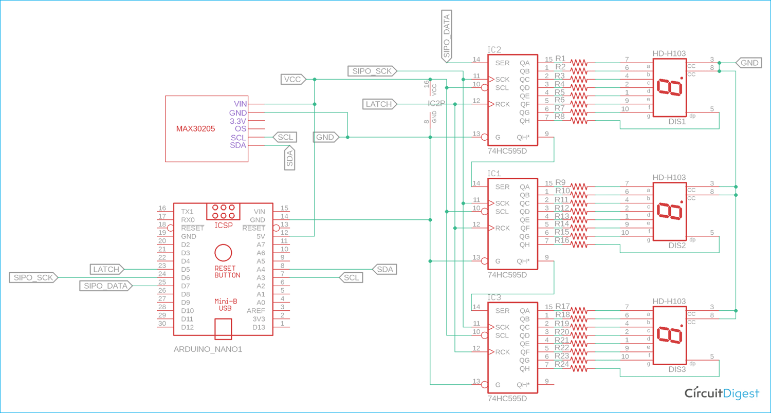
The complete circuit diagram to connect Arduino with Body Temperature sensor MAX30205 is shown below. The circuit is very simple, but since we have used 7-segment displays, it looks a bit complicated. 7-Segment Displays with Arduino is a great way to display your value big and bright with very low cost. But you can also display these values on an OLED or LCD if you wish so.
The Arduino Nano is connected with three 74HC595. Three 74HC595 are cascaded together to save additional output pins from the Arduino Nano for connecting three 7-Seg displays. We have previously used 74HC595 with Arduino in many other projects like the Arduino Clock, LED Board Display, Arduino snake game, etc. to name a few.
The MAX30205 module board requires additional pull-up resistors since it communicates with the I2C protocol. However, few module boards do not require additional pullup as the pull-up resistors are already given inside the module. Therefore, one needs to confirm whether the module board has internal pull-up resistors or it requires an external pull up additionally. The board that is used in this project already has the inbuilt pull-up resistors inside the module board.
Interfacing Arduino with MAX30205 Body Temperature Sensor
The sensor that is used over here is the MAX30205 from maxim integrated. MAX30205 temperature sensor accurately measures temperature with 0.1°C Accuracy (37°C to 39°C). The sensor works with the I2C protocol.
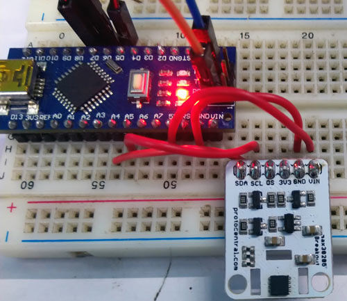
The module board can work with 5 or 3.3V. However, the board is configured to be used with 5V operating voltage. It also includes a logic level shifter, since the sensor itself supports a maximum of 3.3V as power or data communication-related purposes.
On the output, three 74HC595, 8-bit shift registers are used to interface three 7-Segment displays with the Arduino NANO. The pin diagram can be shown in the below image-

The pin description of the 74HC595 can be seen in the below table-
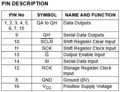
The QA to QH are the data output pins that are connected with the 7-Seg displays. Since three 74HC595 are cascaded together, the Data input pin (PIN14) of the first shift register will be connected with the Arduino NANO and the Serial data output pin will provide the data to the next shift register. This serial data connection will be continued up to the third 74HC595.
Programming MAX30205 with Arduino
The complete program for this tutorial can be found at the bottom of this page. The explanation of this code is as follows. First, we include the standard Arduino I2C library header file.
#include <Wire.h>
The above line will include the Arduino contributed library from protocentral. This library has important functions to communicate with the MAX30205 sensor. The library is taken from the below GitHub link-
https://github.com/protocentral/ProtoCentral_MAX30205
After importing the library, we define MAX30205 object data as shown below-
#include "Protocentral_MAX30205.h"
MAX30205 tempSensor;
Next two lines are important to set the parameters. The below line will provide temperature in Fahrenheit if set true. For showing the result in Celsius, the line needs to be set false.
const bool fahrenheittemp = true; // I'm showing the temperature in Fahrenheit, If you want to show the temperature in Celsius the make this variable false.
Below line needs to be configured if common cathode type 7-segment displays are being used in the hardware. Make it false if common anode is used.
const bool commonCathode = true; // I'm using common Cathode 7segment if you use common Anode then change the value into false.
const byte digit_pattern[17] =
{
  // 74HC595 Outpin Connection with 7segment display.
  // Q0 Q1 Q2 Q3 Q4 Q5 Q6 Q7
  // a  b  c  d  e  f  g  DP
  0b11111100,  // 0
  0b01100000,  // 1
  0b11011010,  // 2
  0b11110010,  // 3
  0b01100110,  // 4
  0b10110110,  // 5
  0b10111110,  // 6
  0b11100000,  // 7
  0b11111110,  // 8
  0b11110110,  // 9
  0b11101110,  // A
  0b00111110,  // b
  0b00011010,  // C
  0b01111010,  // d
  0b10011110,  // E
  0b10001110,  // F
  0b00000001   // .
};
The above array is used to store the digit pattern for the 7-Segment displays.
In the setup function, after setting the pin modes of 74HC595 pins, the I2C protocol and temperature sensor reading is initialized.
void setup() {
  // put your setup code here, to run once:
  // set the serial port at 9600
  Serial.begin(9600);
  delay(1000);
  // set the 74HC595 Control pin as output
  pinMode(latchPin, OUTPUT);    //ST_CP of 74HC595
  pinMode(clkPin, OUTPUT);      //SH_CP of 74HC595
  pinMode(dtPin, OUTPUT);       //DS of 74HC595
  // initialize I2C Libs
  Wire.begin();
  // start MAX30205 temperature read in continuos mode, active mode
  tempSensor.begin();
}
In the loop, the temperature is being read by the function tempSensor.getTemperature() and stored in a float variable named temp. After that, if Fahrenheit temperature mode is selected, the data is converted from Celsius to Fahrenheit. Then, three digits from the converted sensed temperature data are further separated into three individual digits. To do this, below lines of codes are used-
 // saperate 3 digits from the current temperature (like if temp = 31.23c, )
  int dispDigit1=(int)temp/10;      // digit1 3
  int dispDigit2=(int)temp%10;      // digit2 1
  int dispDigit3=(temp*10)-((int)temp*10);  //digit3 2
Now, the separated three digits are sent to the 7-segment displays using the 74HC595 shift registers. Since the LSB first showed into the third 7-segment display via the third 74HC595, the 3rd digit is first transmitted. To do this, the latched pin is pulled low and the data is submitted to the 74HC595 by the function shiftOut();
In the same way, remaining second and first digits are also sent to the respective 74HC595, thus remaining two 7-segment displays. After sending all the data, the latch pin is released and pulled high to confirm the end of data transmission. The respective codes can be seen below -
  // display digits into 3, 7segment display.
  digitalWrite(latchPin, LOW);
  if(commonCathode == true){
    shiftOut(dtPin, clkPin, LSBFIRST, digit_pattern[dispDigit3]);
    shiftOut(dtPin, clkPin, LSBFIRST, digit_pattern[dispDigit2]|digit_pattern[16]);   // 1. (Digit+DP)
    shiftOut(dtPin, clkPin, LSBFIRST, digit_pattern[dispDigit1]);
  }else{
    shiftOut(dtPin, clkPin, LSBFIRST, ~(digit_pattern[dispDigit3]));
    shiftOut(dtPin, clkPin, LSBFIRST, ~(digit_pattern[dispDigit2]|digit_pattern[16]));   // 1. (Digit+DP)
    shiftOut(dtPin, clkPin, LSBFIRST, ~(digit_pattern[dispDigit1]));
  }
  digitalWrite(latchPin, HIGH);
Arduino Body Temperature Meter – Testing
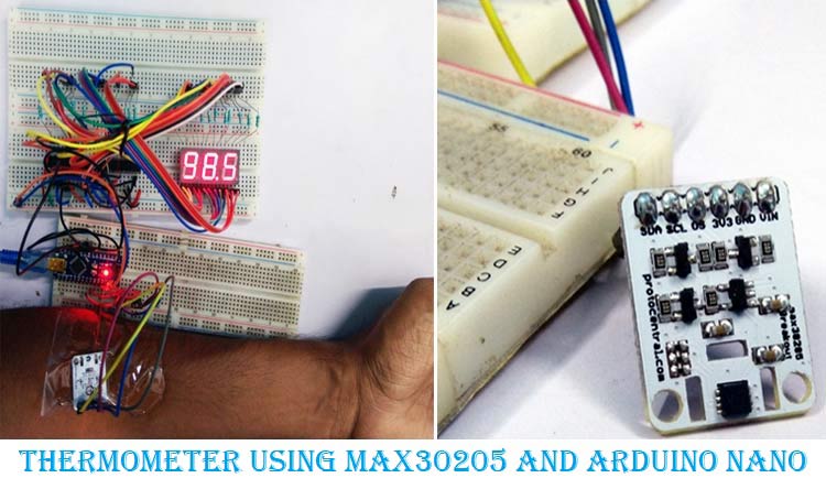
The circuit is constructed in two sets of breadboards as you can see below. When we place the finger on the sensor, the temperature is sensed and the output is shown into a 7 segment display, here the value is 92.1*F.
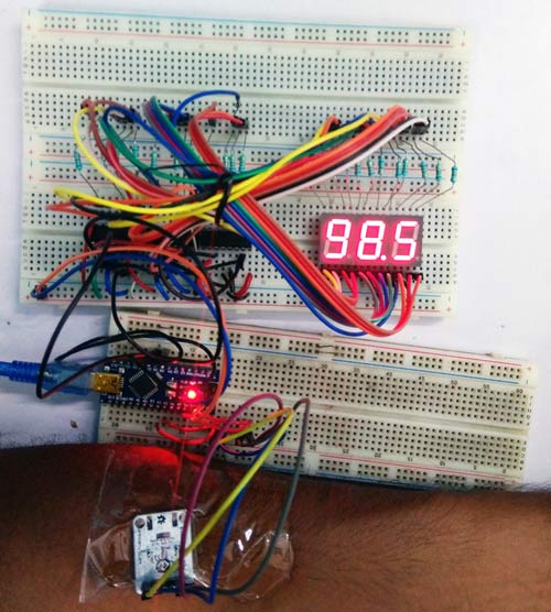
The complete working of the project can be found in the video linked below. Hope you enjoyed building the project and learned something useful. If you have any questions, leave them in the comment section below or use our forums.
/*
 * This program Print temperature on 3, 7segment display
 * Hardware Connections (Breakoutboard to Arduino Nano):
 * Vin  - 5V (3.3V is allowed)
 * GND - GND
 * MAX30205 SDA - A4
 * MAX30205 SCL - A5
 * 74HC595 ST_CP - D5
 * 74HC595 SH_CP - D6
 * 74HC595 DS - D7
 *
 */
#include <Wire.h>
#include "Protocentral_MAX30205.h" // Arduino Contributed Libs (https://github.com/protocentral/ProtoCentral_MAX30205)
// define MAX30205 objectData
MAX30205 tempSensor;
// Show the temperature in Fahrenheit
const bool fahrenheittemp = true; // I'm showing the temperature in Fahrenheit, If you want to show the temperature in Celsius then make this variable false.
// set the 7segment type (common Cathode or Anode)
const bool commonCathode = true; // I'm using common Cathode 7segment if you use common Anode then change the value into false.
// alpha-digit pattern for a 7-segment display
const byte digit_pattern[17] =
{
  // 74HC595 Output Connection with 7segment display.
  // Q0 Q1 Q2 Q3 Q4 Q5 Q6 Q7
  // a  b  c  d  e  f  g  DP
  0b11111100,  // 0
  0b01100000,  // 1
  0b11011010,  // 2
  0b11110010,  // 3
  0b01100110,  // 4
  0b10110110,  // 5
  0b10111110,  // 6
  0b11100000,  // 7
  0b11111110,  // 8
  0b11110110,  // 9
  0b11101110,  // A
  0b00111110,  // b
  0b00011010,  // C
  0b01111010,  // d
  0b10011110,  // E
  0b10001110,  // F
  0b00000001   // .
};
//Pin connected to ST_CP of 74HC595
int latchPin = 5;
//Pin connected to SH_CP of 74HC595
int clkPin = 6;
//Pin connected to DS of 74HC595
int dtPin = 7;
void setup() {
  // put your setup code here, to run once:
  // set the serial port at 9600
  Serial.begin(9600);
  delay(1000);
  // set the 74HC595 Control pin as output
  pinMode(latchPin, OUTPUT);    //ST_CP of 74HC595
  pinMode(clkPin, OUTPUT);      //SH_CP of 74HC595
  pinMode(dtPin, OUTPUT);       //DS of 74HC595
  // initialize I2C Libs
  Wire.begin();
  // start MAX30205 temperature read in continuous mode, active mode
  tempSensor.begin();
}
void loop() {
  float temp = tempSensor.getTemperature(); // read temperature for every 5ms
  if( fahrenheittemp == true){
    temp = (temp * 1.8) + 32 ; // convert the temperature from Celcius to Farenhite using formula of [ T(°C) × 1.8 + 32 ]
    Serial.print(temp ,2);
    Serial.println("°f" );
  }else{
    Serial.print(temp ,2);
    Serial.println("°c" );
  }
  // saperate 3 digits from the current temperature (like if temp = 31.23c, )
  int dispDigit1=(int)temp/10;      // digit1 3
  int dispDigit2=(int)temp%10;      // digit2 1
  int dispDigit3=(temp*10)-((int)temp*10);  //digit3 2
/*
  Serial.print(temp);
  Serial.print(" ");
  Serial.print(dispDigit1);
  Serial.print(" ");
  Serial.print(dispDigit2);
  Serial.print(" ");
  Serial.println(dispDigit3);
*/
  // display digits into 3, 7segment display.
  digitalWrite(latchPin, LOW);
  if(commonCathode == true){
    shiftOut(dtPin, clkPin, LSBFIRST, digit_pattern[dispDigit3]);
    shiftOut(dtPin, clkPin, LSBFIRST, digit_pattern[dispDigit2]|digit_pattern[16]);   // 1. (Digit+DP)
    shiftOut(dtPin, clkPin, LSBFIRST, digit_pattern[dispDigit1]);
  }else{
    shiftOut(dtPin, clkPin, LSBFIRST, ~(digit_pattern[dispDigit3]));
    shiftOut(dtPin, clkPin, LSBFIRST, ~(digit_pattern[dispDigit2]|digit_pattern[16]));   // 1. (Digit+DP)
    shiftOut(dtPin, clkPin, LSBFIRST, ~(digit_pattern[dispDigit1]));
  }
  digitalWrite(latchPin, HIGH);
  delay(500);
}
