As a kid I was fascinated by a toy music car which gets triggered when you clap your hands, and then as I grew up I wondered if we can use the same to toggle lights and fans in our home. It would be cool to just turn on my Fans and lights by just clapping hands instead of walking my lazy self to the switch board. But often times it would malfunction as this circuit will respond to any loud noise in the environment, like a loud radio or for my neighbor’s lawn mower. Although building a clap switch is also a fun project to do.
It was then, when I came across this Whistle Detecting method in which the circuit will detect for whistle. A whistle unlike other sounds will have a uniform frequency for a particular duration and hence can be distinguished from speech or music. So in this tutorial we will learn how to detect whistle sound by interfacing Sound Sensor with Arduino and when a whistle is detected we will toggle an AC lamp through a relay. Along the way we will also learn how sound signals are received by microphone and how to measure frequency using Arduino. Sounds interesting right so let’s get started with Arduino based Home Automation Project.
Materials Required
- Arduino UNO
- Sound Sensor Module
- Relay Module
- AC Lamp
- Connecting Wires
- Breadboard
Sound Sensor Working
Before we dive into the hardware connection and code for this Home Automation Project, let’s take a look at the sound sensor. The sound sensor used in this module is shown below. The working principle of most sound sensors available in the market is similar to this, although the appearance might change a bit.
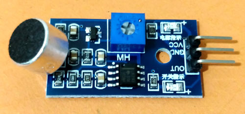
As we know the primitive component in a sound sensor is the microphone. A microphone is type of transducer which converters sound waves (acoustical energy) into electrical energy. Basically diaphragm inside the microphone vibrates to the sound waves in the atmosphere which produces electrical signal on its output pin. But these signals will be of very low magnitude (mV) and hence cannot be processed directly by a microcontroller like Arduino. Also by default sound signals are analog in nature hence the output from the microphone will be a sine wave with variable frequency, but microcontrollers are digital devices and hence work better with square wave.
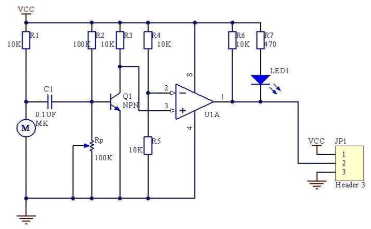
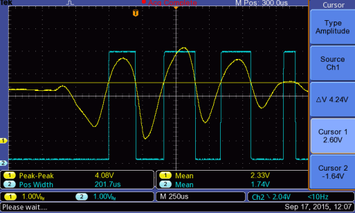
To amplify these low signal sine waves and convert them into square waves the module uses the on-board LM393 Comparator module as shown above. The low voltage audio output from the microphone is supplied to one pin of the comparator through an amplifier transistor while a reference voltage is set on the other pin using a voltage divider circuit involving a potentiometer. When the audio output voltage from microphone exceeds the preset voltage the comparator goes high with 5V (operating voltage), else the comparator stays low at 0V. This way low signal sine wave can be converter to high voltage (5V) square wave. The oscilloscope snapshot below shows the same where the yellow wave is the low signal sine wave and the blue on is the output square wave. The sensitivity can be controlled by varying the potentiometer on the module.
Measuring Audio Frequency on Oscilloscope
This sound sensor module will convert the sound waves in the atmosphere into square waves who’s frequency will be equal to the frequency of the sound waves. So by measuring the frequency of the square wave we can find the frequency of the sound signals in the atmosphere. To make sure things are working as they are supposed I connected the sound sensor to my scope to probe its output signal as shown in the video below.
I turned on the measurement mode on my scope to measure the frequency and used an Android application (Frequency Sound Generator) from the Play Store to generate sound signals of known frequency. As you can see in the above GID the scope was able to measure sound signals with a pretty decent accuracy, the value of frequency displayed in the scope is very close to one displayed on my phone. Now, that we know the module is working lets proceed with interfacing Sound sensor with Arduino.
Whistle Detector Arduino Circuit Diagram
The complete circuit diagram for the Arduino Whistle Detector Switch circuit using Sound Sensor is show below. The circuit was drawn using Fritzing software.

The Sound sensor and the Relay module is powered by the 5V pin of the Arduino. The output pin of the Sound sensor is connected to the digital pin 8 of the Arduino, this is because of the timer property of that pin and we will discuss more about this in the programming section. The Relay module is triggered by pin 13 which is also connected to the in-built LED on the UNO board.
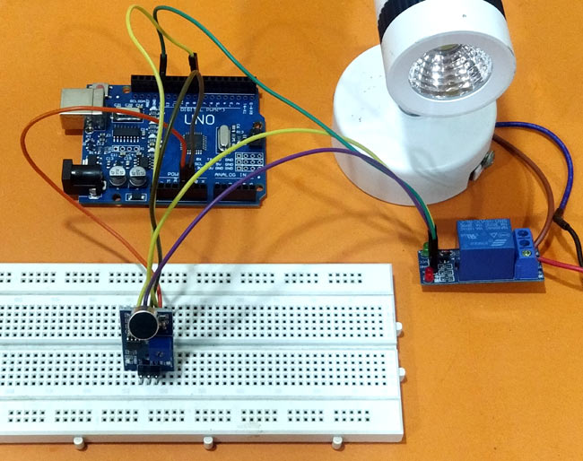
On the AC supply side the neutral wire is directly connected to the Common(C) pin of the Relay module while the Phase is connected to the Normally Open (NO) pin of the relay through the AC load (light bulb). This way when the relay is triggered the NO pin will be connected with C pin and thus the light bulb will glow. Else the blub will remain turned off. Once the connections are made, my hardware looked something like this.
Warning: Working with AC circuit could get dangerous, be cautious while handling live wires and avoid short circuits. A circuit breaker or adult supervision is recommended for people who are not experienced with electronics. You have been warned!!
Measuring Frequency with Arduino
Similar to our scope reading the frequency of the incoming square waves, we have to program out Arduino to calculate frequency. We have already learnt how to do this in our Frequency Counter tutorial using the pulse in function. But in this tutorial we will be using the Freqmeasure library to measure frequency to get accurate results. This library uses the internal timer interrupt on pin 8 to measure how long a pulse stays ON. Once the time is measure we can calculate the frequency using the formulae F=1/T. However since we are using the library directly we need not get into the register details and math of how frequency is measured. Library can be downloaded from the link below:
The above link will download a zip file, you can then add this zip file to your Arduino IDE by following the path Sketch -> Include Library -> Add .ZIP Library.
Note: Using the library will disable the analogWrite functionality on pin 9 and 10 on UNO since the timer will be occupied by this library. Also these pins will change if other boards are used.
Programming your Arduino for detecting Whistle
The complete program with a Demonstration Video can be found at the bottom of this page. In this heading I will explain the program by breaking it into small snippets.
Like always we begin the program by including the required libraries and declaring the required variables. Make sure you have added the FreqMeasure.h library already as explained in above heading. The variable state represents the state of the LED and the variables frequency and continuity is used to output the measured frequency and its continuity respectively.
#include <FreqMeasure.h>//https://github.com/PaulStoffregen/FreqMeasure
double sum=0;
int count=0;
bool state = false;
int frequency;
int continuity =0;
Inside the void setup function, we begin the serial monitor at 9600 baud rate for debugging. Then use the FreqMeasure.begin() function to initialize the pin 8 for measuring the frequency. We also declare that pin 13 (LED_BUILTIN) is output.
void setup() {
  Serial.begin(9600);
  FreqMeasure.begin(); //Measures on pin 8 by default
  pinMode(LED_BUILTIN, OUTPUT);
}
Inside the infinite loop, we keep listening on pin 8 using the function FreqMeasure.available(). If there is an incoming signal we measure the frequency using the FreqMeasure.read(). To avoid error due to noise we measure 100 samples and taken an average of that. The code to do the same is shown below.
  if (FreqMeasure.available()) {
    // average several reading together
    sum = sum + FreqMeasure.read();
    count = count + 1;
    if (count > 100) {
      frequency = FreqMeasure.countToFrequency(sum / count);
      Serial.println(frequency);
      sum = 0;
      count = 0;
    }
  }
You can use the Serial.println() function here to check the value of the frequency for your whistle. In my case the value received was from 1800Hz to 2000Hz. The whistle frequency of most people will fall in this particular range. But even other sounds like music or voice might fall under this frequency so to distinguish them we will monitor for continuity. If the frequency is continuous for 3 times then we confirm it to be a whistle sound. So, if the frequency is between 1800 to 2000 then we increment the variable called continuity.
    if (frequency>1800 && frequency<2000)
    { continuity++; Serial.print("Continuity -> "); Serial.println(continuity); frequency=0;}
If the value of continuity reaches or exceeds three, then we change the state of the LED by toggling the variable called state. If the state is already true we change it to false and vise versa.
    if (continuity >=3 && state==false)
      {state = true; continuity=0; Serial.println("Light Turned ON"); delay(1000);}

    if (continuity >=3 && state==true)
      {state = false; continuity=0; Serial.println("Light Turned OFF"); delay(1000);}
Arduino Whistle Detector Working
Once the code and the hardware are ready we can start testing it. Make sure the connections are correct and power up the module. Open the serial monitor and start whistling, you can notice the value of continuity being incremented and finally turning on or off the Lamp. A sample snap shot of my serial monitor is shown below.
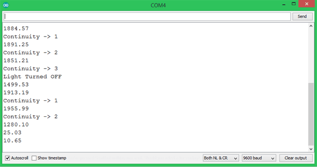
When the serial monitor says Light turned on the pin 13 will be made high and the relay will be trigged to turn on the Lamp. Similarly the lamp will be turned off when the serial monitor says Light turned off. Once you have tested the working you can power the set-up using a 12V adapter and start controlling your AC Home Appliance using whistle.
The complete working of this project can be found at the video linked below. Hope you understood the tutorial and enjoyed learning something new. If you have any problem in getting things work, leave them in the comment section or use our forum for other technical quires.
/*Arduino Whitsle Detector Switch Program
* Detects the whistles from pin 8 and toggles pin 13
* Dated: 31-5-2019
* Website: www.circuitdigest.com
*/
#include <FreqMeasure.h>//https://github.com/PaulStoffregen/FreqMeasure
void setup() {
Serial.begin(9600);
FreqMeasure.begin(); //Measures on pin 8 by default
pinMode(LED_BUILTIN, OUTPUT);
}
double sum=0;
int count=0;
bool state = false;
float frequency;
int continuity =0;
void loop() {
if (FreqMeasure.available()) {
// average several reading together
sum = sum + FreqMeasure.read();
count = count + 1;
if (count > 100) {
frequency = FreqMeasure.countToFrequency(sum / count);
Serial.println(frequency);
sum = 0;
count = 0;
}
}
if (frequency>1800 && frequency<2000)
{ continuity++; Serial.print("Continuity -> "); Serial.println(continuity); frequency=0;}
if (continuity >=3 && state==false)
{state = true; continuity=0; Serial.println("Light Turned ON"); delay(1000);}
if (continuity >=3 && state==true)
{state = false; continuity=0; Serial.println("Light Turned OFF"); delay(1000);}
digitalWrite(LED_BUILTIN, state);
}