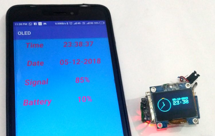
Most of us would be familiar with the 16×2 Dot matrix LCD display that is used in many projects to display some information to the user. But these LCD displays have a lot of limitation in what they can do. In this tutorial, we will use OLED to display some basic information from the Android smartphone like Time, date, network strength and battery status. This project provides a basic idea and framework to build an Arduino based SmartWatch and can be further extended to display incoming calls, messages and many more on OLED display.
So here we fetch some information from an Android mobile phone by using an android application and then send this information to OLED display by using Bluetooth Module and Arduino Pro Mini. Android smartphone already has inbuilt Bluetooth to send the data and at receiving end we have used Bluetooth module HC-06 with Arduino. Bluetooth module HC-05 can also be used in place of HC-06.
In Android application, data is fetched from the mobile phone and sent to the Arduino as a String. Now after receiving the data, Arduino decodes the incoming string of bytes and put it in the temporary variables to display it on OLED display. In OLED display we have created some graphics to show the values, learn more about using OLED display with Arduino here.
Hardware Required
- 128×64 OLED display Module (SSD1306)
- Arduino ( we have used Arduino Pro Mini. But we can use any Arduino Board)
- Bluetooth HC05/HC06
- Connecting Wires
- 3.7v Li-On Battery
- Jumper
Getting to know about OLED Displays
The term OLED stands for “Organic Light emitting diode” it uses the same technology that is used in most of our televisions but has fewer pixels compared to them. It is real fun to have these cool looking display modules to be interfaced with the Arduino since it will make our projects look cool. We have covered a full Article on OLED displays and its types here. Here, we are using a Monochrome 4-pin SSD1306 0.96” OLED display. This Display can only work with the I2C mode.
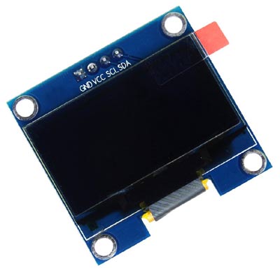
VCC -> 3.3v
GND -> GND
SDA -> SDA (Physical pin 3)
SCL -> SCL (Physical pin 5
Arduino community has already given us a lot of Libraries which can be directly used to make this a lot simpler. I tried out a few libraries and found that the Adafruit_SSD1306 Library was very easy to use and had a handful of graphical options hence we will use the same in this tutorial. Here we also need to install one more library in Arduino IDE which can be downloaded from here GFX Graphics Library.
OLED looks very cool and can be easily interfaced with other microcontrollers to build some interesting projects:
- Interfacing SSD1306 OLED Display with Raspberry Pi
- Interfacing SSD1306 OLED Display with Arduino
- Internet Clock using ESP32 and OLED Display
- Automatic AC Temperature Controller using Arduino, DHT11 and IR Blaster
Circuit Diagram
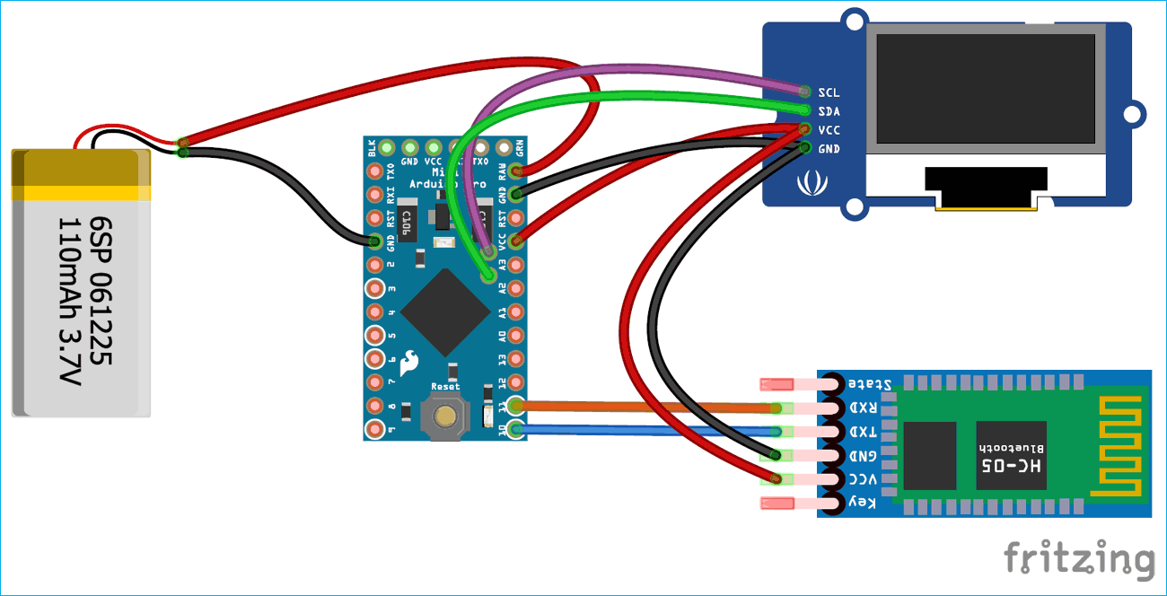
The Circuit Diagram for using 4 pin SSD1306 OLED with Arduino is simple and is shown below
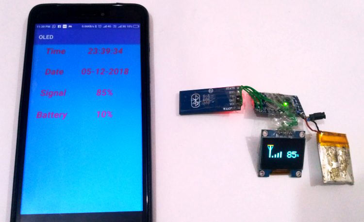
Here we have used a Arduino Pro Mini board to control all the operations. The reason to choose Arduino pro mini is that it can operate at 3.3v power supply. The 4 pin OLED and Bluetooth module HC-06 can also work on 3.3v, so all of these modules can be powered by a single 3.7v Li-on. Li-on battery is the compact and light weight battery, and is the perfect choice for wearable devices. And here we also make something wearable in this project like a simple smartwatch, which can be synced with your smartphone.
Now one question arises about power supply is that here all the modules are working on 3.3v but li-ion battery is giving 3.7v which may damage the modules. So to solve this problem we have applied battery’s 3.7v supply to a raw pin of Arduino pro mini which can convert that voltage to 3.3v.
Android App for sending data to Arduino over Bluetooth
For this Arduino based Smart Watch, we have created a Android App in Android Studio, this app can be downloaded from here. So just download and install this app in your Android Smart phone and then enable the Bluetooth and pair the HC-06 module with your phone. It may ask for passcode to pair the HC-06 bluetooth module, default passcode is 1234 or 0000.
Now open the OLED app and select paired Bluetooth device HC-06, as shown in the below image:
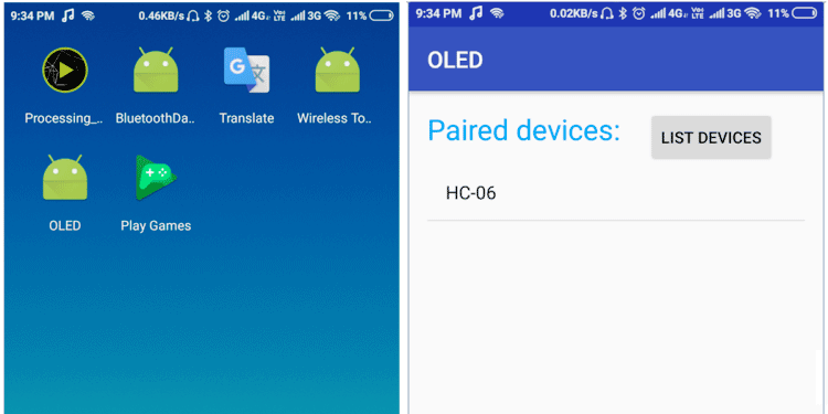
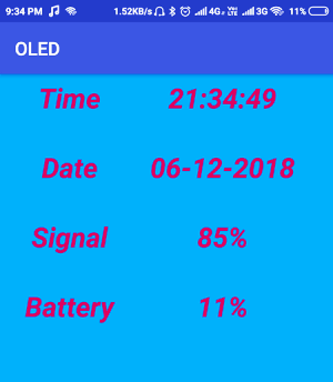
Now OLED app will display the data fetched from the android phone as shown below:
Programming Arduino for OLED Smart Watch
Complete program with a demonstration video is given at the end of this project here we have explained few parts of code.
First download and the Adafruit Library and the GFX library from Github using the links below
Then start with including all the required libraries
#include<SoftwareSerial.h>
SoftwareSerial Serial1(10, 11);

#include <SPI.h>
#include <Wire.h>
#include <Adafruit_GFX.h>
#include "Adafruit_SSD1306.h"

#define OLED_RESET 4
Adafruit_SSD1306 display(OLED_RESET);
After this we have defined some macros and variables for different operations.
#define NUMFLAKES 10
#define XPOS 0
#define YPOS 1
#define DELTAY 2

#define LOGO16_GLCD_HEIGHT 16
#define LOGO16_GLCD_WIDTH  16
String str = "";
byte h = 0;
byte m = 0;
byte S = 0;
String dmy, time, network, battery, inNumber, s;
byte centerX = 24;
byte centerY = 39;
byte Radius = 24;

double RAD = 3.141592 / 180;
double LR = 89.99;
After this write a function for analog clock.
void showTimeAnalog(int center_x, int center_y, double pl1, double pl2, double pl3)
{
  double x1, x2, y1, y2;
  x1 = center_x + (Radius * pl1) * cos((6 * pl3 + LR) * RAD);
  y1 = center_y + (Radius * pl1) * sin((6 * pl3 + LR) * RAD);
  x2 = center_x + (Radius * pl2) * cos((6 * pl3 - LR) * RAD);
  y2 = center_y + (Radius * pl2) * sin((6 * pl3 - LR) * RAD);
  display.drawLine((int)x1, (int)y1, (int)x2, (int)y2, WHITE);
}
Then there is another function for digital Clock.
void digitalClock()
{
  display.setTextSize(1);
  display.setTextColor(WHITE);
  display.setCursor(60, 20);
  display.println(dmy);
  display.setTextSize(2);
  display.setCursor(60, 30);
  display.println(time);
  display.display();
  delay(2000);
}
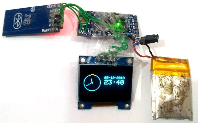
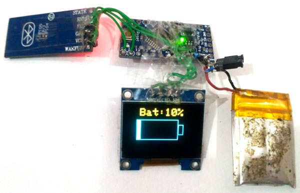
Then OLED will display the Battery status in Numeric and Graphic Forms using the function below.
void Battery()
{
  display.clearDisplay();
  display.setTextSize(2);
  display.setTextColor(WHITE);
  display.setCursor(20, 0);
  display.print("Bat:");
  display.print(battery);
  display.print("%");
  display.drawRect(14, 20, 80, 40, WHITE);
  display.drawRect(94, 30, 10, 20, WHITE);
  display.fillRect(14, 20, (int)(8 * (battery.toInt()) / 10), 40, WHITE);
  display.display();
  delay(2000);
}
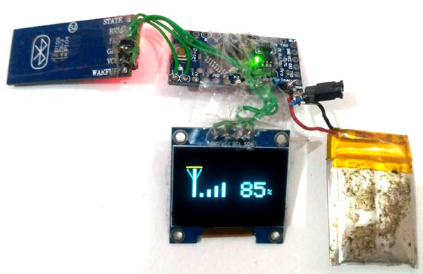
Below function is used for displaying status of Network in Numeric and Graphic Form as well.
void Network()
{
  display.clearDisplay();
  display.drawLine(5, 15, 25, 15, WHITE);
  display.drawLine(5, 15, 14, 30, WHITE);
  display.drawLine(25, 15, 17, 30, WHITE);
  display.fillRect(14, 15, 4, 40, WHITE);
  int net = network.toInt() / 20;
  int x1 = 24, y1 = 50, x2 = 4, y2 = 5;
  .......
  .....
After that in setup function, we have initialiase all communications and modules that we have used in this project.
void setup()
{
  Serial.begin(9600);
  display.begin(SSD1306_SWITCHCAPVCC, 0x3C);  // initialize with the I2C addr 0x3D (for the 128x64)
  display.clearDisplay();
  Serial1.begin(9600);
  Serial1.println("System Ready");
}
And in loop function, we have received data from android mobile and decoded that data and sent them to OLED display.
void loop(){
  Serial1.println("1234");
  delay(1000);
  while (Serial1.available() > 0){
    char ch = Serial1.read();
    str += ch;
    if (ch == '$'){
      dmy = str.substring(str.indexOf("#") + 1, str.indexOf(" "));
      time = str.substring(str.indexOf(" ") + 1, str.indexOf(",") - 3);
      network = str.substring(str.indexOf(",") + 1, str.indexOf(",,"));
      battery = str.substring(str.indexOf(",,") + 2, str.indexOf(",,,"));
      inNumber = str.substring(str.indexOf(",,,") + 3, str.indexOf("$"));
      s = time.substring(time.indexOf(" ") + 1, time.indexOf(" ") + 3);
      h = s.toInt();
      s = time.substring(time.indexOf(" ") + 4, time.indexOf(" ") + 6);
      m = s.toInt();
      s = time.substring(time.indexOf(" ") + 7, time.indexOf(" ") + 9);
      S = s.toInt();
      str = "";}
  }
  display.clearDisplay();
  display.drawCircle(centerX, centerY, Radius, WHITE);
  showTimeAnalog(centerX, centerY, 0.1, 0.5, h * 5 + (int)(m * 5 / 60));
  showTimeAnalog(centerX, centerY, 0.1, 0.78, m);
  // showTimePin(centerX, centerY, 0.1, 0.9, S);
  digitalClock();
  Battery();
  Network();
}
This is how we can connect OLED with and Smartphone wirelessly and can send or sync whatever data we want from the smart phone to OLED.
#include<SoftwareSerial.h>
SoftwareSerial Serial1(10, 11);
#include <SPI.h>
#include <Wire.h>
#include <Adafruit_GFX.h>
#include "Adafruit_SSD1306.h"
#define OLED_RESET 4
Adafruit_SSD1306 display(OLED_RESET);
#define NUMFLAKES 10
#define XPOS 0
#define YPOS 1
#define DELTAY 2
#define LOGO16_GLCD_HEIGHT 16
#define LOGO16_GLCD_WIDTH 16
String str = "";
byte h = 0;
byte m = 0;
byte S = 0;
String dmy, time, network, battery, inNumber, s;
byte centerX = 24;
byte centerY = 39;
byte Radius = 24;
double RAD = 3.141592 / 180;
double LR = 89.99;
void showTimeAnalog(int center_x, int center_y, double pl1, double pl2, double pl3)
{
double x1, x2, y1, y2;
x1 = center_x + (Radius * pl1) * cos((6 * pl3 + LR) * RAD);
y1 = center_y + (Radius * pl1) * sin((6 * pl3 + LR) * RAD);
x2 = center_x + (Radius * pl2) * cos((6 * pl3 - LR) * RAD);
y2 = center_y + (Radius * pl2) * sin((6 * pl3 - LR) * RAD);
display.drawLine((int)x1, (int)y1, (int)x2, (int)y2, WHITE);
}
void digitalClock()
{
display.setTextSize(1);
display.setTextColor(WHITE);
display.setCursor(60, 20);
display.println(dmy);
display.setTextSize(2);
display.setCursor(60, 30);
display.println(time);
display.display();
delay(2000);
}
void Battery()
{
display.clearDisplay();
display.setTextSize(2);
display.setTextColor(WHITE);
display.setCursor(20, 0);
display.print("Bat:");
display.print(battery);
display.print("%");
display.drawRect(14, 20, 80, 40, WHITE);
display.drawRect(94, 30, 10, 20, WHITE);
display.fillRect(14, 20, (int)(8 * (battery.toInt()) / 10), 40, WHITE);
display.display();
delay(2000);
}
void Network()
{
display.clearDisplay();
display.drawLine(5, 15, 25, 15, WHITE);
display.drawLine(5, 15, 14, 30, WHITE);
display.drawLine(25, 15, 17, 30, WHITE);
display.fillRect(14, 15, 4, 40, WHITE);
int net = network.toInt() / 20;
int x1 = 24, y1 = 50, x2 = 4, y2 = 5;
for (int i = 1; i <= net; i++)
{
display.fillRect(x1, y1, x2, y2, WHITE);
x1 += 10;
y1 -= 5;
y2 += 10;
y2 -= 5;
}
display.setTextSize(3);
display.setTextColor(WHITE);
display.setCursor(80, 34);
display.print(network);
display.setTextSize(1);
display.setCursor(117, 44);
display.println("%");
display.display();
delay(2000);
}
void setup()
{
Serial.begin(9600);
display.begin(SSD1306_SWITCHCAPVCC, 0x3C); // initialize with the I2C addr 0x3D (for the 128x64)
display.clearDisplay();
Serial1.begin(9600);
Serial1.println("System Ready");
}
void loop(){
Serial1.println("1234");
delay(1000);
while (Serial1.available() > 0){
char ch = Serial1.read();
str += ch;
if (ch == '$'){
dmy = str.substring(str.indexOf("#") + 1, str.indexOf(" "));
time = str.substring(str.indexOf(" ") + 1, str.indexOf(",") - 3);
network = str.substring(str.indexOf(",") + 1, str.indexOf(",,"));
battery = str.substring(str.indexOf(",,") + 2, str.indexOf(",,,"));
inNumber = str.substring(str.indexOf(",,,") + 3, str.indexOf("$"));
s = time.substring(time.indexOf(" ") + 1, time.indexOf(" ") + 3);
h = s.toInt();
s = time.substring(time.indexOf(" ") + 4, time.indexOf(" ") + 6);
m = s.toInt();
s = time.substring(time.indexOf(" ") + 7, time.indexOf(" ") + 9);
S = s.toInt();
str = "";}
}
display.clearDisplay();
display.drawCircle(centerX, centerY, Radius, WHITE);
showTimeAnalog(centerX, centerY, 0.1, 0.5, h * 5 + (int)(m * 5 / 60));
showTimeAnalog(centerX, centerY, 0.1, 0.78, m);
// showTimePin(centerX, centerY, 0.1, 0.9, S);
digitalClock();
Battery();
Network();
}
Comments
Did you find a solution yet on the problem with the APK file?
Did you find a solution for this problem yet? I'll be needing this android, or any android application to let my smartwatch work for a schoolproject.
There are many similar
There are many similar software on Google Play store, you can use anyone
Reply on AISHA
Thanks for the suggestion, but which app could I use without changing anything in the code? Or is there any application which lets me just change the code a little instead of recoding the whole thing? I'm not that good at code yet, and I really need to use this for a schoolproject.
konsa app ?.....pls tell me
konsa app ?.....pls tell me which app from playstore.....i need that app right now....its very important.
APK file not being installed
Dear Saddam,
I can't find a way to download your APK-file for the android application I'll be needing to let this project work. I really appriciate your codes, and information. But is there any kind of solution for this problem I am having?
Sir pls give me apk file...
Sir pls give me apk file....its really important now.......tnx for advance.
relogio
Hi, I'm from Brazil and I'm using google translator so sorry for any errors. What should I do in the code to be able to use a 128x32 oled? because in my code the only step is that everything appears very large, and another doubt would have some app to indicate to use with the clock? if everything works out I'll make a video for youtube and I'll point out your page, my friend.
Bro no ones going to try this
Bro no ones going to try this if you cant install the app



hey, we tried your project, everything is all right just we got stuck in oled apk it is not getting installed please help asap if you get this....