In many cases, touch sensors are used instead of push buttons. The advantage is that we don't have to provide force to press a button, and we can activate a key without touching it using touch sensors. Touch sensing technology is becoming popular day by day. And within the last decade or so, it has become difficult to imagine the world without touch-sensitive electronics. Both resistive and capacitive touch methods can be employed to develop a touch sensor, and in this article, we will discuss a crude way of making a capacitive touch sensor with ESP32, previously we have also build a Capacitive touch button with Raspberry pi.
Though application-specific touch sensors can be a little complicated, the fundamental principle underlying this technology stays the same, so in this article, we will be focusing on developing our capacitive touch sensor with the help of our favourite ESP32 and a piece of copper-clad board.
In the previous tutorial, we have done Control Home Lights with Touch using TTP223 Touch Sensor and Arduino UNO, Now in this project, we are building a Touch sensor for ESP32 but the same can be used for Arduino as well. Also, we previously used touch-based input methods using capacitive touch pads with different microcontrollers such as Touch Keypad Interfacing with ATmega32 Microcontroller and Capacitive TouchPad with Raspberry Pi, you can also check them out if interested.
What is a Capacitive Touch Sensor and How Does it Work?
Capacitors come in many forms. The most common once comes in the form of a leaded package or a surface mount package but to form a capacitance, we need conductors separated by a dielectric material. Thus, it's easy to create one. A good example would be the one which we are going to develop in the following example.
Considering the etched PCB as the conductive material, the sticker is acting as a dielectric material, so now the question remains, how touching the copper pad causes the capacitance to change in such a way that the touch-sensor controller is able to detect? A human finger, of course.
Well, there are mainly two reasons: First, one includes the dielectric properties of our finger, the second one is because of the conductive properties of our finger. We are going to be using a capacitive based touch. So, we will turn our focus towards the capacitive based touch sensor. But before we discuss all this, it's important to note that there isn't any conduction taking place, and the finger is insulated, because of the paper used in the sticker. So, the finger isn't able to discharge the capacitor.
Finger Acting as Dielectric:
It's common knowledge that a capacitor has a constant value which can be realized by the area of the two conducting plates, the distance between the plates, and it's dielectric constant. We cannot change the area of the capacitor just by touching it but we can sure change the dielectric constant of the capacitor because a human finger has a different dielectric constant than the material displaying it. In our case, it's air, we are displacing air with our fingers. If you are asking how? It's because the dielectric constant of the air 1006 at sea level room temperature and the dielectric constant of the finger is much higher around 80 because a human finger consists of mostly water. So, the interaction of the finger with the capacitor's electric field causes an increase in dielectric constant hence the capacitance increases.
Now that we have understood the principal, let's move on to the making of actual PCBs.
Building a Four-Way Capacitive Touch Sensor
The capacitive touch sensor used in this project has four channels, and it's easy to make. Below we have mentioned the detailed process to make one.
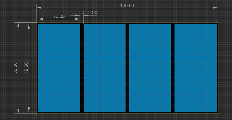
First, we made the PCB for the sensor with the help of the Eagle PCB design tool, which looks something like the image below.
With the help of the dimensions and Photoshop, we made the template and finally the sticker for the sensor, which looks something like the image below,

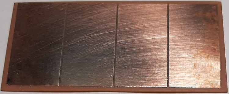
Now, as we are done with the sticker, we move on to making the actual clad board template which we are going to be using for making our PCB with, which looks something like the below image,

Now we can print this file and proceed with the processes of making a homemade PCB. IF you are new, you can check out the article on how to build PCB at home. You can also download the required PDF and Gerber files from below link
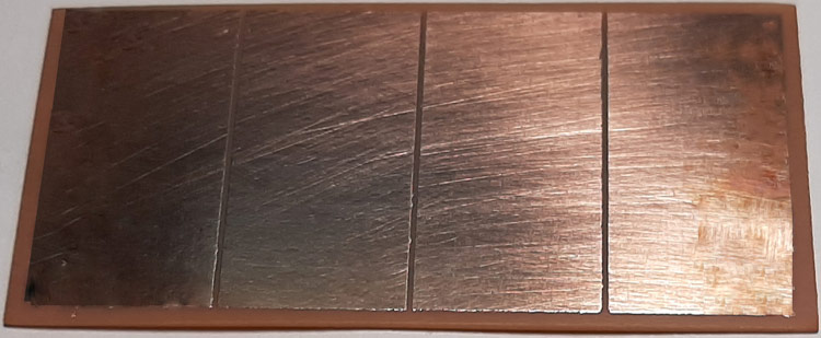
Once done, the actual Etched PCB looks like the image below.
Now it's time to drill some holes, and we connect some wires with the PCB. So that we can connect it with the ESP32 board. Once done, it looks like the image below.
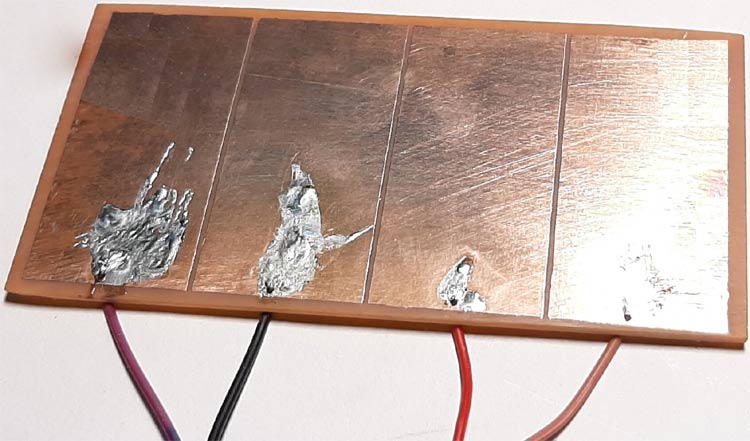
As we did not put via’s in the PCB, solder got all over the place while soldering, we rectified our mistake by putting a drill hole on the PCB, which you can find in the above download section. Finally, it was time to put the sticker on and make it final. Which looks something like the image below.
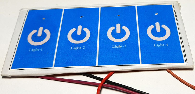
Now we are done with the Touch panel, it's time to move on to making the Control Circuit for the touch panel.
Materials Required for ESP32 Touch Controlled Circuit
The components required to build the controller section using ESP32 is given below, you should be able to find most of them in the local hobby store.
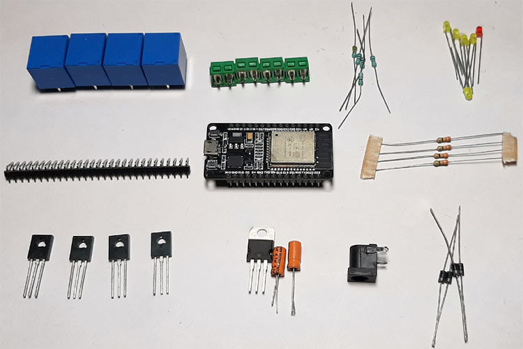
I have also listed the components in the table below with type and quantity required, since we are interfacing a four-channel touch sensor and controlling four AC loads, we will be using 4 relays to switch the AC load and 4 transistors to build the relay driver circuits.
|
Sl.No |
Parts |
Type |
Quantity |
|
1 |
Relay |
Switch |
4 |
|
2 |
BD139 |
Transistor |
4 |
|
3 |
Screw Terminal |
Screw Terminal 5mmx2 |
4 |
|
4 |
1N4007 |
Diode |
5 |
|
5 |
0.1uF |
Capacitor |
1 |
|
6 |
100uF,25V |
Capacitor |
2 |
|
7 |
LM7805 |
Voltage Regulator |
1 |
|
8 |
1K |
Resistor |
4 |
|
9 |
560R |
Resistor |
4 |
|
10 |
Amber LED |
LED |
4 |
|
11 |
Male Header |
Connector |
4 |
|
12 |
Female Header |
Connector |
30 |
|
13 |
Red LED |
LED |
1 |
|
14 |
ESP32 Dev Board V1 |
ESP32 Board |
1 |
|
12 |
Clad Board |
Generic 50x 50mm |
1 |
|
13 |
Jumper Wires |
Wires |
4 |
|
14 |
Connecting Wires |
Wires |
5 |
Control Circuit for our Capacitive Touch Sensor
The below image shows the complete circuit diagram for our ESP32 based touch sensor.
As you can see, it is a very simple circuit with very minimum components required.

As it’s a simple touch sensor circuit, it can be useful in places where you want to interact with a device via touch, for example, instead of using a typical board-mounted switch, you can turn on/off your appliances with touch.
In the schematic, A DC barrel jack is used as an input where we provide the necessary power required to power the circuit, from there we have our 7805 Voltage regulator which is converting the unregulated DC input to a constant 5V DC through which we are providing the power to the ESP32 module.
Next, in the schematic, we have our touch connectors on pin 25, 26, 27, 28, where we are going to connect the touchpad.
Next, we have our relays which are switched via a BD139 transistor, the diode D2, D3, D4, D5 is there to protects the circuit from any transient’s voltage which is generated when the relay toggles, the diodes in this configuration are known as the fly-back diode/freewheeling diode. The 560R resistors at the base of each transistor are used to limit the flow of current through the base.
PCB Design for the Capacitive Touch Sensor Circuit
The PCB for our touch sensor circuit was designed for a single-sided board. We have used Eagle to design my PCB, but you can use any Design software of your choice. The 2D image of our board design is shown below.

A sufficient trace diameter was used to make the power tracks, which is used to flow the current through the circuit board. We put the screw terminal at the top because it's much easier to connect your load that way, and the power connector, which is a DC barrel jack was placed at the side, which also gives easy access. The complete Design file for Eagle along with the Gerber can be downloaded from the link below.
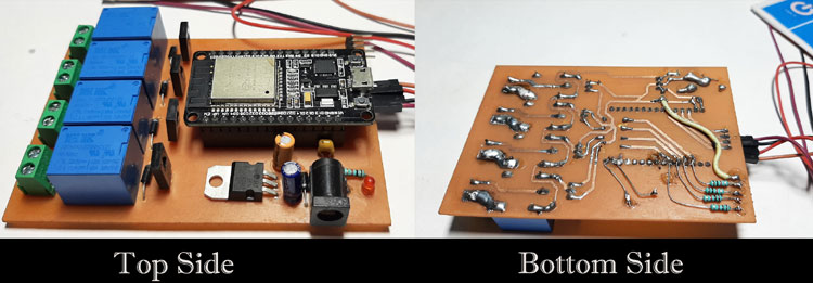
Now that our Design is ready, its time to etch and solder the board. After the etching, drilling, and soldering process are finished, the board looks like the image shown below,
Arduino Code for ESP32 Based Capacitive Touch Sensor
For this project, we will program the ESP32 with a custom code which we will describe shortly. The code is very simple and easy to use,
We start by defining all the required pins, in our case, we define the pins for our touch sensors and relays.
#define Relay_PIN_1 15
#define Relay_PIN_2 2
#define Relay_PIN_3 4
#define Relay_PIN_4 16
#define TOUCH_SENSOR_PIN_1 13
#define TOUCH_SENSOR_PIN_2 12
#define TOUCH_SENSOR_PIN_3 14
#define TOUCH_SENSOR_PIN_4 27
Next, in the setup section, we start by initializing the UART for debugging, next we have introduced a delay of 1S which gives us a little time for opening a Serial Monitor window. Next, we use the Arduinos pinMode function to make the Relay pins as output, which marks the end of the Setup() section.
void setup() {
  Serial.begin(115200);
  delay(1000);
  pinMode(Relay_PIN_1, OUTPUT);
  pinMode(Relay_PIN_2, OUTPUT);
  pinMode(Relay_PIN_3, OUTPUT);
  pinMode(Relay_PIN_4, OUTPUT);
}
We start our loop section with an if statement, the builtin function touchRead(pin_no) is used to determine if a pin was touched or not. The touchRead(pin_no) function returns an integer value ranges (0 - 100), the value stays near 100 all the time, but if we touch the selected pin, the value drops to near zero, and with the help of the changing value, we can determine if the particular pin was touched by a finger or not.
In the if statement, we are checking for any change in the integer values, and if the value reaches below 28, we can be sure that we have acknowledged a touch. Once the if statement becomes true, we wait for 50ms and check the parameter again, this will help us to determine if the sensor value was trigger falsely, after that, we invert the status of the pin by using the digitalWrite(Relay_PIN_1, !digitalRead(Relay_PIN_1)) method, and the rest of the code stays the same.
if ( touchRead(TOUCH_SENSOR_PIN_1) < 28) {
    if ( touchRead(TOUCH_SENSOR_PIN_1) < 28) {
      Serial.println("Sensor one is touched");
      digitalWrite(Relay_PIN_1, !digitalRead(Relay_PIN_1));
    }
  }
  else if (touchRead(TOUCH_SENSOR_PIN_2) < 28) {
    if (touchRead(TOUCH_SENSOR_PIN_2) < 28) {
      Serial.println("Sensor Two is touched");
      digitalWrite(Relay_PIN_2, !digitalRead(Relay_PIN_2));
    }
  }
  else if ( touchRead(TOUCH_SENSOR_PIN_3) < 28) {
    if (touchRead(TOUCH_SENSOR_PIN_3) < 28) {
      Serial.println("Sensor Three is touched");
      digitalWrite(Relay_PIN_3, !digitalRead(Relay_PIN_3));
    }
  }
  else if (touchRead(TOUCH_SENSOR_PIN_4) < 28) {
    if (touchRead(TOUCH_SENSOR_PIN_4) < 28) {
      Serial.println("Sensor Four is touched");
      digitalWrite(Relay_PIN_4, !digitalRead(Relay_PIN_4));
    }
  }
Finally, we end our code with another 200 ms of blocking delay.
Testing the ESP32 Based Touch Sensor Circuit
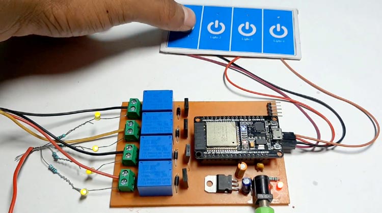
As this is a very simple project, the test set is very simple, as you can see, I have connected 4 LEDs with resistors which are acting as loads, as it's connected with the relay, you can easily connect any load up to 3Amps.
Further Enhancements
Though the PCB is simple, there's still room for improvements as you can see from the bottom side of the actual PCB, I have connected many resistors in an attempt to connect four indication LEDs, and the size of the PCB can also be reduced if that becomes a requirement,
Hope you enjoyed the article and learned something useful. If you have any questions, you can leave them in the comment section below or use our forums to post other technical questions.
#define Relay_PIN_1 15
#define Relay_PIN_2 2
#define Relay_PIN_3 4
#define Relay_PIN_4 16
//All relay pin definitions
#define TOUCH_SENSOR_PIN_1 13
#define TOUCH_SENSOR_PIN_2 12
#define TOUCH_SENSOR_PIN_3 14
#define TOUCH_SENSOR_PIN_4 27
// all touch sensor pin definitions
void setup() {
  Serial.begin(115200); //Begin the UART
  delay(1000); // give me time to bring up serial monitor
  pinMode(Relay_PIN_1, OUTPUT);
  pinMode(Relay_PIN_2, OUTPUT);
  pinMode(Relay_PIN_3, OUTPUT);
  pinMode(Relay_PIN_4, OUTPUT);
  // all the relay pins set as output
}
void loop() {
  /*
     Uncomment for debug
      Serial.println(" ");
      Serial.println("#############################");
      Serial.print("Button1: ");
      Serial.println(touchRead(TOUCH_SENSOR_PIN_1));  // get value of Touch 0 pin = GPIO 4
      Serial.print("Button2: ");
      Serial.println(touchRead(TOUCH_SENSOR_PIN_2));
      Serial.print("Button3: ");
      Serial.println(touchRead(TOUCH_SENSOR_PIN_3));
      Serial.print("Button4: ");
      Serial.println(touchRead(TOUCH_SENSOR_PIN_4));
      Serial.println("#############################");
      Serial.println(" ");
  */
  if ( touchRead(TOUCH_SENSOR_PIN_1) < 28) { // check if the value reaches belo 28
    delay(50);
    if ( touchRead(TOUCH_SENSOR_PIN_1) < 28) { //again check if the value reaches below 28
      Serial.println("Sensor one is touched");
      digitalWrite(Relay_PIN_1, !digitalRead(Relay_PIN_1));
    }
  }
  else if (touchRead(TOUCH_SENSOR_PIN_2) < 28) {
    delay(50);
    if (touchRead(TOUCH_SENSOR_PIN_2) < 28) {
      Serial.println("Sensor Two is touched");
      digitalWrite(Relay_PIN_2, !digitalRead(Relay_PIN_2));
    }
  }
  else if ( touchRead(TOUCH_SENSOR_PIN_3) < 28) {
    delay(50);
    if (touchRead(TOUCH_SENSOR_PIN_3) < 28) {
      Serial.println("Sensor Three is touched");
      digitalWrite(Relay_PIN_3, !digitalRead(Relay_PIN_3));
    }
  }
  else if (touchRead(TOUCH_SENSOR_PIN_4) < 28) {
    delay(50); // works as a debounce delay.
    if (touchRead(TOUCH_SENSOR_PIN_4) < 28) {
      Serial.println("Sensor Four is touched");
      digitalWrite(Relay_PIN_4, !digitalRead(Relay_PIN_4));
    }
  }
  delay(200);
}