There are many pulse-oximeter sensors available in the market for medical purposes, and in one of our previous projects, we also made an IoT-based Heart Rate Monitor where the data is sent from a device to the cloud. Now, here in this project, we will do the same thing but differently with a different mindset. We will make the project using a MAX30100 sensor and an OLED display that will display the output in the same way as a proper Pulse-Oximeter sensor displays. The objective of this project is to make the whole process simple, for this reason, we are going to use an Arduino Nano. Our goal is to make the device as compact as possible and smaller in size. So that it can be handy to use in the time of need. Previously, we have also built other heart rate monitors using pulse sensors. Also, if you are interested in other Covid-19 related projects, you can check out the Human body thermometer, Smart IR Thermometer for fever monitoring, and Wall-Mount Temperature scanner that we build earlier.
This is the Pulse-Oximeter sensor-based project same as the available medical device. However, This project is not for medical purposes. Please do not use this to evaluate the patient's condition and always use a proper medical-grade device. This is only intended for hobby and learning purposes.
MAX30100 Sensor
Before going directly into the project let’s introduce the major component, the MAX30100 sensor, which is a simple module that communicates with the I2C bus line with the microcontroller and provides the SpO2 and Pulse information to the host microcontroller unit. In simple terms, this sensor can identify the oxygen saturation Thus, this module has two integrated functions, Pulse rate monitoring and provides oxygen saturation level of the blood in a non-invasive form.
It uses photodetectors and optical elements where red or green IR LED modulates the LED pulses. The LED current is configurable from 0 to 50mA. The image given below shows the MAX30100 sensor.
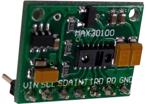
The above sensor module works with the 1.8V to the 5.5V range. The pull-up resistors for the I2C pins are included in
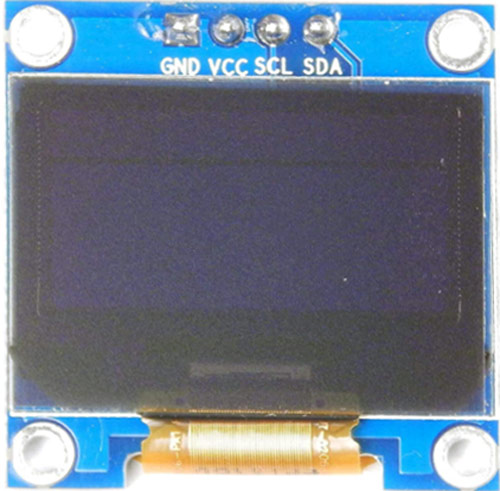
OLED displays are very common in electronics. We are using OLED display as all available pulse oximeter devices available in the market use OLED display. For this project, we are using 1.3 Inch I2C based OLED display. It has a 128x64 Resolution with a controlling chip of SSD1306.
Below is the image of the OLED Display.
 the module.
OLED Display
Components Required to Build Arduino Based Pulse Oximeter Circuit
- Arduino Nano
- 2 pcs – 4.7k resistor for I2C pull-up
- MAX30100 Sensor
- OLED Display SSD1306 based 128x32 Resolution
- 5V adequate power supply unit with the rated current of at least 300mA
Schematic of the Oximeter Circuit

This is a very simple schematic. The pin A5 and A4 of the Arduino Nano are connected with pulse oximeter sensor 30100 and OLED Display with the SDA and SCL pins. Both pins are using a pull-up resistor of 4.7k value.
Code explanation
This code uses many libraries and all are important. The libraries are MAX30100 Pulse oximeter sensor library, Wire. h for the I2C, Adafruit_GFX.h for showing animation on the display, Adafruit_SSD1306.h for the display driver, and Fonts/FreeSerif9pt7b.h for the front.
Those libraries are included at the beginning of the code.
#include <Wire.h>
#include "MAX30100_PulseOximeter.h"
#include <Adafruit_GFX.h>
#include <Adafruit_SSD1306.h>
#include <Fonts/FreeSerif9pt7b.h>
Next, two definitions are ENABLE_MAX30100 which is used for setting the MAX30100 enable bit as 1. Next, the SCREEN_WIDTH and SCREEN_HEIGHT. This has to be the exact value of the OLED Display resolution.
#define ENABLE_MAX30100 1
#define SCREEN_WIDTH 128 // OLED display width, in pixels
#define SCREEN_HEIGHT 32 //64 // OLED display height, in pixels
A callback function is defined when the pulse is detected by the sensor which is available as the function given.
void onBeatDetected()
{
  Serial.println("Beat!");
  heart_beat(&xPos);
}
In the application setup following things are done:
- Activating the display driver on the I2C line
- Clearing the display, setting the text size, text color, and setting up the cursor position
- Printing the Pulse Oximeter
- Setting up the Heartbeat animation location
- Initializing the MAX30100
- Setting up the cursor position for the heartbeat and spo2 information.
Activating the display driver on the I2C line:
// SSD1306_SWITCHCAPVCC = generate display voltage from 3.3V internally
  if (!display.begin(SSD1306_SWITCHCAPVCC, SCREEN_ADDRESS)) {
    Serial.println(F("SSD1306 allocation failed"));
    for (;;); // Don't proceed, loop forever
  }
Clearing the display, setting the text size, text color, and setting up the cursor position:
  display.clearDisplay();
  display.setTextSize(1);
  display.setTextColor(WHITE);
  display.setCursor(20, 18);
Printing the Pulse Oximeter Text On the OLED Display:
display.print("Pulse OxiMeter");
Setting up the Heartbeat animation location:
  int temp1 = 0;
  int temp2 = 40;
  int temp3 = 80;
  heart_beat(&temp1);
  heart_beat(&temp2);
  heart_beat(&temp3);
  xPos = 0;
Initializing the MAX30100:
#if ENABLE_MAX30100
  // Initialize the PulseOximeter instance
  // Failures are generally due to an improper I2C wiring, missing power supply
  // or wrong target chip
  if (!pox.begin()) {
    Serial.println("FAILED");
    for (;;);
  } else {
    Serial.println("SUCCESS");
  }
Setting up the MAX30100 LED Current and registering the beat detection callback function:
pox.setIRLedCurrent(MAX30100_LED_CURR_7_6MA);
  // Register a callback for the beat detection
  pox.setOnBeatDetectedCallback(onBeatDetected);
Get BPM and SPO2 Value by Calling two Functions:
By calling this function on the loop section, we can get the updated value from the sensor.
pox.getHeartRate(); and pox.getSpO2();
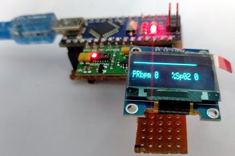
Arduino Based Pulse Oximeter Circuit Testing
The circuit is made in a small compact Vero board. The data is perfectly displayed on the display. Without any data, the screen looks like this.
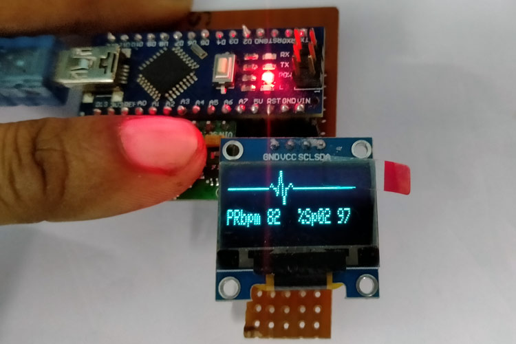
As we can see in the below image, the SPO2 level is showing 97% and the heartbeat is showing 82 bits per minute when measured and the animation is also changed.
/*
   File Name: pulse-oxymeter.ino
   Created on: 28-Jan-2021
   Author: Noyel Seth (noyelseth@gmail.com)
*/
#include <Wire.h>
#include "MAX30100_PulseOximeter.h"
#include <Adafruit_GFX.h>
#include <Adafruit_SSD1306.h>
#include <Fonts/FreeSerif9pt7b.h>
#define ENABLE_MAX30100 1
#define SCREEN_WIDTH 128 // OLED display width, in pixels
#define SCREEN_HEIGHT 32 //64 // OLED display height, in pixels
// Declaration for an SSD1306 display connected to I2C (SDA, SCL pins)
// The pins for I2C are defined by the Wire-library.
// On an arduino UNO:       A4(SDA), A5(SCL)
// On an arduino MEGA 2560: 20(SDA), 21(SCL)
// On an arduino LEONARDO:   2(SDA),  3(SCL), ...
#define OLED_RESET     -1 // 4 // Reset pin # (or -1 if sharing Arduino reset pin)
#define SCREEN_ADDRESS 0x3c ///< See datasheet for Address; 0x3D for 128x64, 0x3C for 128x32
Adafruit_SSD1306 display(SCREEN_WIDTH, SCREEN_HEIGHT, &Wire, OLED_RESET);
#if ENABLE_MAX30100
#define REPORTING_PERIOD_MS     5000
// PulseOximeter is the higher level interface to the sensor
// it offers:
//  * beat detection reporting
//  * heart rate calculation
//  * SpO2 (oxidation level) calculation
PulseOximeter pox;
#endif
uint32_t tsLastReport = 0;
int xPos = 0;
// Callback (registered below) fired when a pulse is detected
void onBeatDetected()
{
  Serial.println("Beat!");
  heart_beat(&xPos);
}
void setup()
{
  Serial.begin(115200);
  Serial.println("SSD1306 128x64 OLED TEST");
  // SSD1306_SWITCHCAPVCC = generate display voltage from 3.3V internally
  if (!display.begin(SSD1306_SWITCHCAPVCC, SCREEN_ADDRESS)) {
    Serial.println(F("SSD1306 allocation failed"));
    for (;;); // Don't proceed, loop forever
  }
  // Show initial display buffer contents on the screen --
  // the library initializes this with an Adafruit splash screen.
  //display.display();
  display.clearDisplay();
  display.setTextSize(1);
  display.setTextColor(WHITE);
  display.setCursor(20, 18);
  // Display static text
  display.print("Pulse OxiMeter");
  int temp1 = 0;
  int temp2 = 40;
  int temp3 = 80;
  heart_beat(&temp1);
  heart_beat(&temp2);
  heart_beat(&temp3);
  xPos = 0;
  display.display();
  delay(2000); // Pause for 2 seconds
  display.cp437(true);
  display.clearDisplay();
  Serial.print("Initializing pulse oximeter..");
#if ENABLE_MAX30100
  // Initialize the PulseOximeter instance
  // Failures are generally due to an improper I2C wiring, missing power supply
  // or wrong target chip
  if (!pox.begin()) {
    Serial.println("FAILED");
    for (;;);
  } else {
    Serial.println("SUCCESS");
  }
  // The default current for the IR LED is 50mA and it could be changed
  //   by uncommenting the following line. Check MAX30100_Registers.h for all the
  //   available options.
  pox.setIRLedCurrent(MAX30100_LED_CURR_7_6MA);
  // Register a callback for the beat detection
  pox.setOnBeatDetectedCallback(onBeatDetected);
  display_data(0, 0);
#endif
}
void loop()
{
#if ENABLE_MAX30100
  // Make sure to call update as fast as possible
  pox.update();
  int bpm = 0;
  int spo2 = 0;
  // Asynchronously dump heart rate and oxidation levels to the serial
  // For both, a value of 0 means "invalid"
  if (millis() - tsLastReport > REPORTING_PERIOD_MS) {
    //Serial.print("Heart rate:");
    bpm = pox.getHeartRate();
    spo2 = pox.getSpO2();
    Serial.println(bpm);
    //Serial.print("bpm / SpO2:");
    Serial.println(spo2);
    //Serial.println("%");
    tsLastReport = millis();
    display_data(bpm, spo2);
  }
#endif
  drawLine(&xPos);
}
void display_data(int bpm, int spo2) {
  display.fillRect(0, 18, 127, 15, SSD1306_BLACK);
  display.setTextSize(1);
  display.setTextColor(WHITE);
  display.setCursor(0, 18);
  // Display static text
  display.print("PRbpm ");
  display.print(bpm);
  display.display();
  display.setTextSize(1);
  display.setTextColor(WHITE);
  display.setCursor(64, 18);
  // Display static text
  display.print("%Sp02 ");
  display.println(spo2);
  display.display();
}
void drawLine(int *x_pos) {
  // Draw a single pixel in white
  display.drawPixel(*x_pos, 8, SSD1306_WHITE);
  display.drawPixel((*x_pos)++, 8, SSD1306_WHITE);
  display.drawPixel((*x_pos)++, 8, SSD1306_WHITE);
  display.drawPixel((*x_pos)++, 8, SSD1306_WHITE);
  display.drawPixel((*x_pos), 8, BLACK);  // -----
  //Serial.println(*x_pos);
  display.fillRect(*x_pos, 0, 31, 16, SSD1306_BLACK);
  display.display();
  delay(1);
  if (*x_pos >= SCREEN_WIDTH) {
    *x_pos = 0;
  }
}
void heart_beat(int *x_pos) {
  /************************************************/
  //display.clearDisplay();
  display.fillRect(*x_pos, 0, 30, 15, SSD1306_BLACK);
  // Draw a single pixel in white
  display.drawPixel(*x_pos + 0, 8, SSD1306_WHITE);
  display.drawPixel(*x_pos + 1, 8, SSD1306_WHITE);
  display.drawPixel(*x_pos + 2, 8, SSD1306_WHITE);
  display.drawPixel(*x_pos + 3, 8, SSD1306_WHITE);
  display.drawPixel(*x_pos + 4, 8, BLACK); // -----
  //display.display();
  //delay(1);
  display.drawPixel(*x_pos + 5, 7, SSD1306_WHITE);
  display.drawPixel(*x_pos + 6, 6, SSD1306_WHITE);
  display.drawPixel(*x_pos + 7, 7, SSD1306_WHITE); // .~.
  //display.display();
  //delay(1);
  display.drawPixel(*x_pos + 8, 8, SSD1306_WHITE);
  display.drawPixel(*x_pos + 9, 8, SSD1306_WHITE); // --
  //display.display();
  //delay(1);
  /******************************************/
  display.drawPixel(*x_pos + 10, 8, SSD1306_WHITE);
  display.drawPixel(*x_pos + 10, 9, SSD1306_WHITE);
  display.drawPixel(*x_pos + 11, 10, SSD1306_WHITE);
  display.drawPixel(*x_pos + 11, 11, SSD1306_WHITE);
  //display.display();
  //delay(1);
  /******************************************/
  display.drawPixel(*x_pos + 12, 10, SSD1306_WHITE);
  display.drawPixel(*x_pos + 12, 9, SSD1306_WHITE);
  display.drawPixel(*x_pos + 12, 8, SSD1306_WHITE);
  display.drawPixel(*x_pos + 12, 7, SSD1306_WHITE);
  //display.display();
  //delay(1);
  display.drawPixel(*x_pos + 13, 6, SSD1306_WHITE);
  display.drawPixel(*x_pos + 13, 5, SSD1306_WHITE);
  display.drawPixel(*x_pos + 13, 4, SSD1306_WHITE);
  display.drawPixel(*x_pos + 13, 3, SSD1306_WHITE);
  //display.display();
  //delay(1);
  display.drawPixel(*x_pos + 14, 2, SSD1306_WHITE);
  display.drawPixel(*x_pos + 14, 1, SSD1306_WHITE);
  display.drawPixel(*x_pos + 14, 0, SSD1306_WHITE);
  display.drawPixel(*x_pos + 14, 0, SSD1306_WHITE);
  //display.display();
  //delay(1);
  /******************************************/
  display.drawPixel(*x_pos + 15, 0, SSD1306_WHITE);
  display.drawPixel(*x_pos + 15, 1, SSD1306_WHITE);
  display.drawPixel(*x_pos + 15, 2, SSD1306_WHITE);
  display.drawPixel(*x_pos + 15, 3, SSD1306_WHITE);
  //display.display();
  //delay(1);
  display.drawPixel(*x_pos + 15, 4, SSD1306_WHITE);
  display.drawPixel(*x_pos + 15, 5, SSD1306_WHITE);
  display.drawPixel(*x_pos + 16, 6, SSD1306_WHITE);
  display.drawPixel(*x_pos + 16, 7, SSD1306_WHITE);
  //display.display();
  //delay(1);
  display.drawPixel(*x_pos + 16, 8, SSD1306_WHITE);
  display.drawPixel(*x_pos + 16, 9, SSD1306_WHITE);
  display.drawPixel(*x_pos + 16, 10, SSD1306_WHITE);
  display.drawPixel(*x_pos + 16, 11, SSD1306_WHITE);
  //display.display();
  //delay(1);
  display.drawPixel(*x_pos + 17, 12, SSD1306_WHITE);
  display.drawPixel(*x_pos + 17, 13, SSD1306_WHITE);
  display.drawPixel(*x_pos + 17, 14, SSD1306_WHITE);
  display.drawPixel(*x_pos + 17, 15, SSD1306_WHITE);
  //display.display();
  //delay(1);
  display.drawPixel(*x_pos + 18, 15, SSD1306_WHITE);
  display.drawPixel(*x_pos + 18, 14, SSD1306_WHITE);
  display.drawPixel(*x_pos + 18, 13, SSD1306_WHITE);
  display.drawPixel(*x_pos + 18, 12, SSD1306_WHITE);
  //display.display();
  //delay(1);
  display.drawPixel(*x_pos + 19, 11, SSD1306_WHITE);
  display.drawPixel(*x_pos + 19, 10, SSD1306_WHITE);
  display.drawPixel(*x_pos + 19, 9, SSD1306_WHITE);
  display.drawPixel(*x_pos + 19, 8, SSD1306_WHITE);
  //display.display();
  //delay(1);
  /****************************************************/
  display.drawPixel(*x_pos + 20, 8, SSD1306_WHITE);
  display.drawPixel(*x_pos + 21, 8, SSD1306_WHITE);
  //display.display();
  //delay(1);
  /****************************************************/
  display.drawPixel(*x_pos + 22, 7, SSD1306_WHITE);
  display.drawPixel(*x_pos + 23, 6, SSD1306_WHITE);
  display.drawPixel(*x_pos + 24, 6, SSD1306_WHITE);
  display.drawPixel(*x_pos + 25, 7, SSD1306_WHITE)
  //display.display();
  //delay(1);
  /************************************************/
  display.drawPixel(*x_pos + 26, 8, SSD1306_WHITE);
  display.drawPixel(*x_pos + 27, 8, SSD1306_WHITE);
  display.drawPixel(*x_pos + 28, 8, SSD1306_WHITE);
  display.drawPixel(*x_pos + 29, 8, SSD1306_WHITE);
  display.drawPixel(*x_pos + 30, 8, SSD1306_WHITE); // -----
  *x_pos = *x_pos + 30;
  display.display();
  delay(1);
}