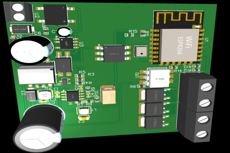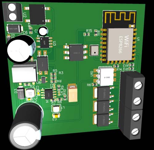
Vayu: A customizable smart air cooler/conditioner controller with IoT integration lets the manufacturers get room for their production of the coolers from building the control unit. In the upcoming days, it is expected that most of our electronic devices will be connected thus leading to the sustainability of this unit.
You can check out our previously built AC controller project,
- Cell Phone Controlled AC using Arduino and Bluetooth
- Automatic AC Temperature Controller using Arduino, DHT11 and IR Blaster
- Temperature Controlled Automatic Switch
Working Principle
The controller is an advanced PI-type controller with anti-windup for self-controlling and adapting. The PID calculations are made at 0.1Hz, this slow rate is okay since the temperature is a sluggish changing variable. The motor control is a phase angle control for smooth dimming and variable AC drive of the motor. Firstly, it looks for an input command from the WiFi, if something new is in the buffer, it reads it and changes its setpoint. Else it goes with the previously set setpoint. Then it calculates the PI value needed for the delay time of the phase angle control, then it drives the motor with Triac, three Triac are parallelly placed for the high current drive of the motor. This phase angle control is also done by the same microcontroller by detecting the zero cross, so there is an interrupt occurring when the microcontroller is not in deep sleep mode, when it wakes up (every 10s) it calculates the PI value and with that, the interrupt mask is set and loops with the drive power of the motor, thus driving the motor with the desired speed. After setting the speed, the microcontroller again goes to sleep mode, and this cycle repeats.
Technology Used in AC Controller
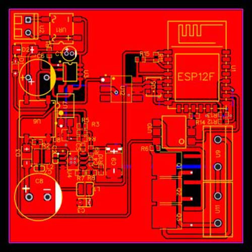
PI control for setting the power of the compressor fan. The drive of the fan is obtained by phase angle control by zero-cross detection. And we made the PCB in EasyEda.
Component Required for Air Cooler Controller
Project Used Hardware

- ESP12 WiFi,
- BT16 triac,
- MOC3021 zero cross triac driver opto-isolator,
- TNY284DG flyback converter IC,
- MP2307 buck regulator IC,
- passive complementary components,
- screw terminals,
- PCBs
Project Used Software
- Arduino IDE,
- EasyEda,
- TI's Webench power Supply Design
Project Hardware Software Selection

First things first for the circuit, we used ESP12 for the MCU along with WiFi connectivity, it's pretty cheap and reliable with high performance. Flyback power converter ICs for power supply to the Controller circuit, Triac to drive AC motor, Zero Cross detector for phase angle control of the AC motors, Screw terminals for plug and play. For software, we used EasyEda for the PCB design, For writing the Firmware we used ArduinoIDE.
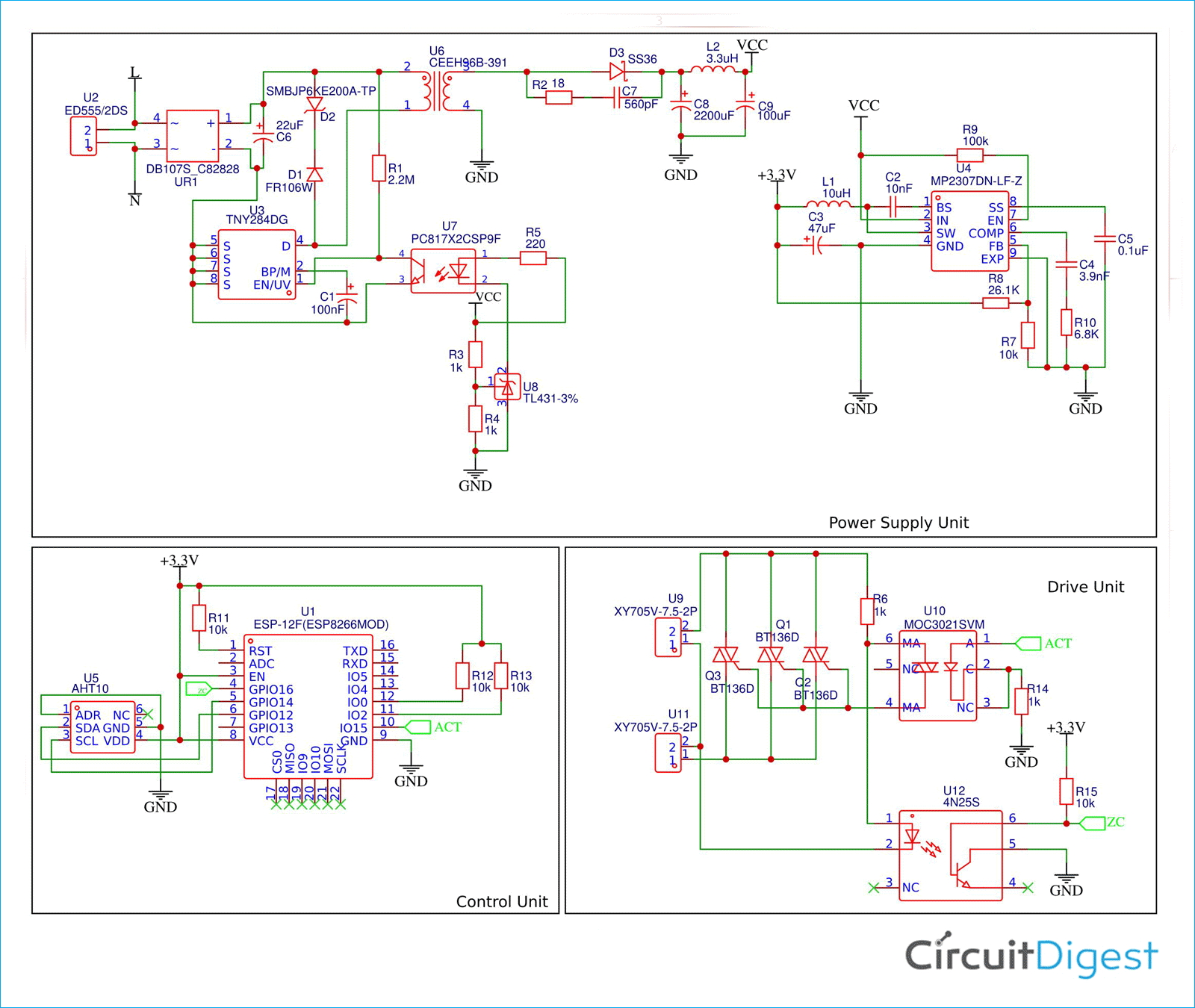
Smart Air Cooler Controller Circuit Diagram
The circuit consists of a power converter side, that reduces the HVAC to useable regulated low voltage DC so that it can power the soft electronics, next section is the main control unit(MCU) which is responsible for controlling the whole unit, from interfacing the sensors to generating signals to drive the AC motors. A small temperature and humidity sensor is attached to the ESP12. For the driving circuit it consists of 3 triacs so that heavy motors can also be driven trough it. And Optocoupler, one for driving the triac, and another for detecting the zero cross of the HVAC.
#define kp -1 //tune according to needs
#define ki -1 //tune according to needs
#include <Adafruit_AHTX0.h>
#include <ESP8266WiFi.h>
#include <ESP8266HTTPClient.h>
#include <WiFiClient.h>
#include "user_interface.h"
extern os_timer_t *timer_list;
timer_list = nullptr;
const char* ssid = "Vayu";
const char* password = "1234";
String server = "http://"; //set according to the server val
boolean flag = false;
Adafruit_AHTX0 aht;
void setup()
{
  WiFi.begin(ssid, password);
  Serial.println("Connecting");
  while(WiFi.status() != WL_CONNECTED) {}
  PCICR |= (1 << PCIE0);
  PCMSK0 |= (1 << PCINT0);
  wifi_fpm_set_wakeup_cb(fpm_wakup_cb_func);
  wifi_fpm_set_sleep_type(LIGHT_SLEEP_T);
  wifi_fpm_open();
  pinMode(15,OUTPUT);
  Serial.begin(115200);
  aht.begin();
}
double error=0, terror=0, dtemp=0;
double pid[100];
void loop()
{
  sensors_event_t humidity, temp;
  if(WiFi.status()== WL_CONNECTED){
      WiFiClient client;
      HTTPClient http;
      http.begin(client, server.c_str());
      drive();
  PCMSK0 ^= (1 << PCINT0);
  wifi_fpm_do_sleep(10000 * 1000);
  }
void pidcalc()
{
  if(http.GET()>0)
  temp=http.getString().toFloat;
  for(int i=0;i<100;i++)
  {
    aht.getEvent(&humidity, &temp);
    error = dtemp-temp.temperature;
    pid[i] = kp*error + ki*terror;
    terror+=error;
  }
}
void drive()
{
  if(flag)
    for(int i=0;i<100;i++)
      for(float z=0.0;z<pid[i];z+=0.5)
      {
        digitalWrite(15, 0);
        delayMicroseconds(z);
        digitalWrite(15, 1);
        delayMicroseconds(z);
        digitalWrite(15, 0);
      }
}

void fpm_wakup_cb_func(void)
{
  PCMSK0 ^= (1 << PCINT0);
  pidcalc();
}
ISR(PCINT0_vect){
  if(PINB & B00000001){
    if(last_CH1_state == 0){
      flag = true;
    }
  }
  else if(last_CH1_state == 1){
    flag = false;
    last_CH1_state = 0;
    }
}


