In the last part, DIY Smartwatch using ESP32, we have looked at how to make some interesting watch faces for our smartwatch project. In this part, we will be looking at how to interface some sensors to our smartwatch and will be interfacing the BH1750 ambient light sensor and the MAX30102 Heart rate sensor. We will be looking at interfacing each of these modules separately.
Prerequisites – Installing Necessary Libraries
All the required libraries are provided in the GitHub repository given below the article. Download them and extract them to the library folder in the Arduino document folder. If you have already installed them, you don’t need to do the previous step except for the display library. For display, you must use the attached TFT_eSPI library. Once it’s done let’s move forward with the interface.
Required Libraries
BH1750 library by Christopher Laws
SparkFun MAX3010X Pulse and Proximity Sensor Library
Interfacing Ambient Light Sensor
First, let’s look at how to interface the ambient light sensor. We will later use this sensor for automatic brightness adjustment. For the ambient light sensor, we have selected the popular BH1750 sensor. BH1750 is pretty cheap and easy to interface with. Not only that, they provide very good accuracy too. Let’s look at the specifications of the sensor itself.
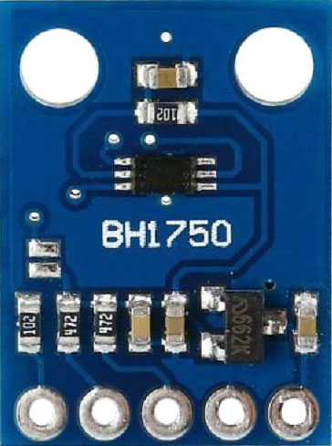
The BH1750 is a 16-bit ambient light sensor that communicates via the I2C protocol. It outputs luminosity measurements in lux. It can measure a minimum of 1 lux and a maximum of 65535 lux. Here’s a list of the BH1750 sensor features.
- I2C bus Interface
- Spectral responsibility is approximately human eye response
- Illuminance to digital converter
- Range: 1 – 65535 lux
- Low current by power down function
- 50Hz / 60Hz Light noise reject-function
- It is possible to select 2 different I2 C slave addresses
- Small measurement variation (+/- 20%)
- The influence of infrared is very small
- Supports continuous measurement mode
- Supports one-time measurement mode
The sensor supports two different measurement modes: continuous measurement mode, and one-time measurement mode. In continuous measurement mode, the sensor continuously measures ambient light values. In one-time measurement mode, the sensor measures the ambient light value once, and then it goes to power down mode. Each mode supports three different resolution modes.
|
Low-Resolution Mode |
4 lux precision |
16ms measurement time |
|
High-Resolution Mode |
1 lux precision |
120ms measurement time |
|
High-Resolution Mode 2 |
0.5 lux precision |
120ms measurement time |
BH1750 Module Pinout
The BH1750 module has a total of 5 pins. In which at least 4 pins are necessary for the interfacing. The pinout of the BH1750 module is as follows:
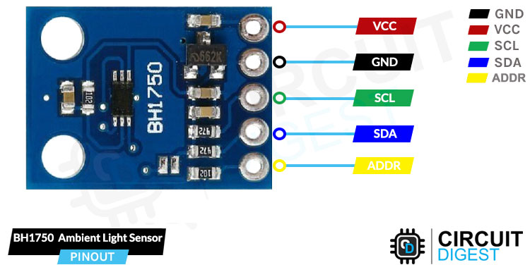
GND Ground connection for the module. Connect to the GND pin of the ESP32.
VCC Provides power for the module. Connect to the 3.3V pin of the ESP32.
SCL Serial Clock pin. Used for providing clock pulse for I2C Communication.
SDA Serial Data pin. Used for transferring Data through I2C communication.
ADDR Address Select pin. Used for configuring I2C communication address.
Circuit Diagram to Interface Ambient Light Sensor with ESP32
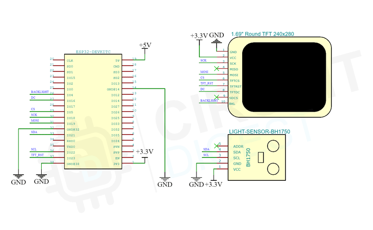
For testing, connect the Ambient light sensor module along with the display module to the ESP32 Devkit as per the Circuit diagram below. Connect the sensor to the I2C line and the display to the SPI bus as we have already done in part one of this project.
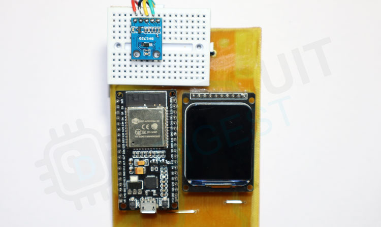
Testing the Ambient Light Sensor
Once all the connections are done, compile the BH1750 example file and upload it to the ESP32. The example will show the light intensity in lux. You can see them below.
Interfacing Heart Rate Sensor
We are going to use the MAX30102 for measuring heart rate. The MAX30102 is a very versatile sensor, and it can also measure body temperature other than heart rate and blood oxygen level. It features two LEDs (one Infrared and one Red), a photodetector, optics, and a low-noise signal processing unit to detect pulse oximetry (SPO2) and heart rate (HR) signals.
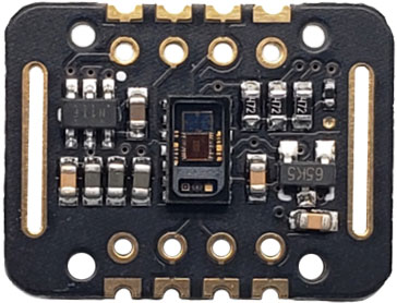
The MAX30102 Sensor shines both the light through the skin and measures the reflection with the photodetector. This method of pulse detection through light is called Photoplethysmogram. The working of the sensor can be divided into two parts: heart rate measurement and blood oxygen level measurement.
The oxygen in the haemoglobin has a specific characteristic that it can absorb IR light. The higher the concentration of haemoglobin, the redder the blood which simply means it can absorb more IR light. As the blood is pumped through the veins in the finger the amount of reflected light changes creating an oscillating waveform. And by measuring this wave we can get a heartbeat reading. Blood oxygen level measurement works on the principle that Red and IR light varies depending upon the oxygen level in your blood. Deoxygenated blood absorbs more RED light while blood with more sufficient oxygen absorbs more IR light. By measuring the ratio between the two we can measure oxygen level.
MAX30102 Module Pinout
The MAX30102 module has a total of 8 pins. This sensor module’s pins are all digital, except VCC and Ground. The pinout of the MAX30102 module is as follows:
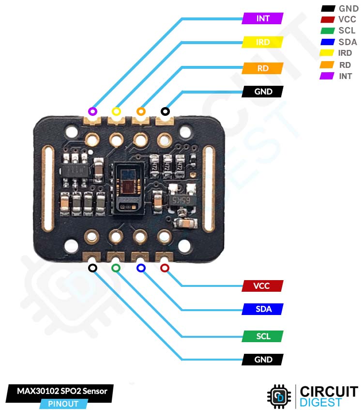
GND Ground connection for the module. Connect to the GND pin of the ESP32.
VCC Provides power for the module. Connect to the 3.3V pin of the ESP32.
SCL Serial Clock pin. Used for providing clock pulse for I2C Communication.
SDA Serial Data pin. Used for transferring Data through I2C communication.
IRD This is the pin connected to the module’s IR LED. This module has a built-in LED driver. Use this pin if you want to manually drive the LED with code, otherwise leave the pin open.
RD The function of this pin is similar to the IRD pin the only difference is that a RED LED is connected to this pin. Leave it untouched if you don't want to drive the LED yourself.
INT Interrupt pin can be programmed to generate an Interrupt on each pulse. This pin is an open drain in nature, so it's pulled high through an onboard resistor. When there is an interrupt, this pin goes low and stays low until the interrupt is cleared.
Circuit Diagram to Interface Heart Rate Sensor with ESP32
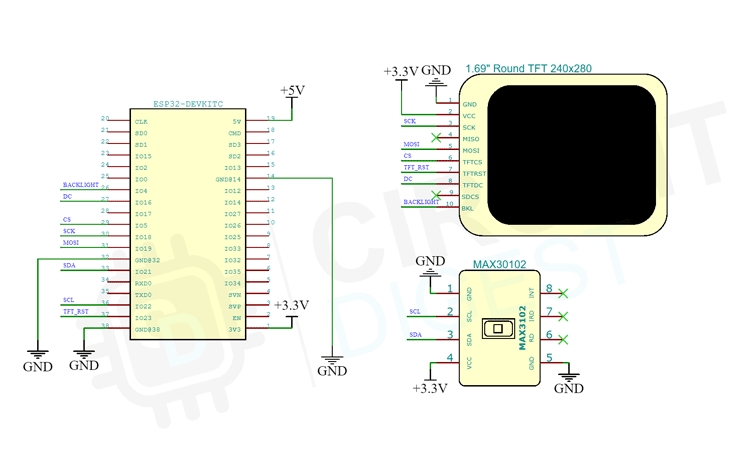
For testing connect the Heart Rate SPO2 sensor module along with the display module to the ESP32 Devkit as per the Circuit diagram below. Connect the sensor to the I2C line and the display to the SPI bus as before.
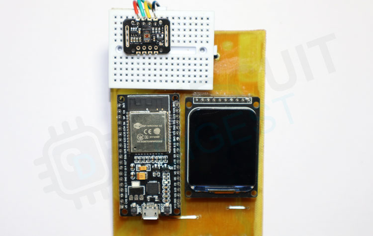
Testing the Heart Rate Sensor
Once all the connections are done compile the MAX30102 example file and upload it to the ESP32. The example will show your heart rate once you place your finger on the sensor for enough time. You can see them below.
In the next part, we will be looking at how to interface the remaining sensors with our smartwatch. You can download all the required files including the libraries from the Circuit Digest GitHub Repo.
//Interface Ambient light sensor with ESP32
#include <SPI.h>
#include <Wire.h>
#include <TFT_eSPI.h> // Modified library for ST7789 Display
#include <BH1750.h> //BH1750 Library
#include "Luxmetervector.h" //Image data
#include "fonts.h" // Font file
#define TFT_GREY 0x5AEB
#define TFT_SKYBLUE 0x067D
#define color1 TFT_WHITE
#define color2  0x8410//0x8410
#define color3 0x5ACB
#define color4 0x15B3
#define color5 0x00A3
#define background 0x65B8
TFT_eSPI tft = TFT_eSPI();       // TFT_eSPI Instance
TFT_eSprite img = TFT_eSprite(&tft);   //Create sprite for faster updation
BH1750 lightMeter;    //BH1750 Instance
int angle = 0;


void setup(void) {
  Wire.begin();//Init I2C
  lightMeter.begin();//Init BH1750 library
  tft.init();
  tft.setRotation(0);
  tft.setSwapBytes(true);
  tft.fillScreen(TFT_BLACK);
  tft.pushImage(0, 0, 240, 280, Lux_meter_vector);
  img.setSwapBytes(true);
  img.createSprite(163, 57);
  img.setTextDatum(4);
  img.setTextColor(0x0081, background);
  img.setFreeFont(&DSEG7_Classic_Bold_30);
}

void loop() {
  int lux = lightMeter.readLightLevel();
  img.fillSprite(background);
  img.drawString(String(lux), 30, 30);
  img.pushSprite(40, 40);
  delay(500);
}
//Interface Heart Rate sensor with ESP32
#include <SPI.h>
#include <Wire.h>
#include <TFT_eSPI.h> // Modified library for ST7789 Display
#include "MAX30105.h" // SparkFun librarry for MAX30102 sensor
#include "heartRate.h" // Heartrate measurement algorithm
#include "hr1.h"
#include "hr2.h"
#include "fonts.h" // Font file
#include "NotoSansBold15.h"
#include "NotoSansBold36.h"
// The font names are arrays references, thus must NOT be in quotes ""
#define FONT_SMALL NotoSansBold15
#define FONT_LARGE NotoSansBold36
#define TFT_GREY 0x5AEB
#define TFT_SKYBLUE 0x067D
#define color1 TFT_WHITE
#define color2  0x8410//0x8410
#define color3 0x5ACB
#define color4 0x15B3
#define color5 0x00A3
#define background 0x65B8
TFT_eSPI tft = TFT_eSPI();       // TFT_eSPI Instance
TFT_eSprite img = TFT_eSprite(&tft);   //Create sprite for faster updation
MAX30105 particleSensor;//MAX30102 instance
const byte RATE_SIZE = 4; //Increase this for more averaging. 4 is good.
byte rates[RATE_SIZE]; //Array of heart rates
byte rateSpot = 0;
long lastBeat = 0; //Time at which the last beat occurred

float beatsPerMinute;
int beatAvg;
bool beat = false;


void setup(void) {
  Serial.begin(115200);
  Serial.println("Initializing...");
  Wire.begin();//Init I2C
  tft.init();
  tft.setRotation(0);
  tft.setSwapBytes(true);
  tft.fillScreen(TFT_BLACK);
  // Initialize sensor
  particleSensor.begin(Wire, I2C_SPEED_FAST);

  particleSensor.setup(); //Configure sensor with default settings
  particleSensor.setPulseAmplitudeRed(0x0A); //Turn Red LED to low to indicate sensor is running
  particleSensor.setPulseAmplitudeGreen(0); //Turn off Green LED

  //  tft.pushImage(0, 0, 240, 280, Lux_meter_vector);
  img.setSwapBytes(true);
  img.setColorDepth(8);
  img.createSprite(240, 280);
  img.setTextDatum(4);
  img.setTextColor(0x0081, background);
  img.setFreeFont(&DSEG7_Classic_Bold_30);
}

void loop() {
  long irValue = particleSensor.getIR();    //Reading the IR value it will permit us to know if there's a finger on the sensor or not
  //Also detecting a heartbeat
  if (checkForBeat(irValue) == true)                        //If a heart beat is detected
  {
    img.fillSprite(TFT_BLACK);                                         //Clear the display
    if (beat == true)
    {
      img.pushImage(0, 0, 240, 280, hr1);
    }
    else
    {
      img.pushImage(0, 0, 240, 280, hr2);
    }
    beat = !beat;
    img.setTextColor(TFT_CYAN, TFT_BLACK);
    img.loadFont(FONT_LARGE);
    img.setCursor(100, 130);
    img.print(beatAvg);
    img.setCursor(140, 145);
    img.loadFont(FONT_SMALL);
    img.print("BPM ");
    img.pushSprite(0, 0);
    //We sensed a beat!
    long delta = millis() - lastBeat;                   //Measure duration between two beats
    lastBeat = millis();

    beatsPerMinute = 60 / (delta / 1000.0);           //Calculating the BPM

    if (beatsPerMinute < 255 && beatsPerMinute > 20)               //To calculate the average we strore some values (4) then do some math to calculate the average
    {
      rates[rateSpot++] = (byte)beatsPerMinute; //Store this reading in the array
      rateSpot %= RATE_SIZE; //Wrap variable

      //Take average of readings
      beatAvg = 0;
      for (byte x = 0 ; x < RATE_SIZE ; x++)
        beatAvg += rates[x];
      beatAvg /= RATE_SIZE;
    }
  }

  else if (irValue < 50000) {      //If no finger is detected it inform the user and put the average BPM to 0 or it will be stored for the next measure
    beatAvg = 0;
    img.loadFont(FONT_SMALL);
    img.setCursor(80, 120);
    img.setTextColor(TFT_CYAN, TFT_BLACK);
    img.fillSprite(TFT_BLACK);
    img.println("Please Place ");
    img.setCursor(80, 140);
    img.println("your finger ");
    img.pushSprite(0, 0);
  }
  Serial.print("IR=");
  Serial.print(irValue);
  Serial.print(", BPM=");
  Serial.print(beatsPerMinute);
  Serial.print(", Avg BPM=");
  Serial.print(beatAvg);

  if (irValue < 50000)
    Serial.print(" No finger?");

  Serial.println();

}


