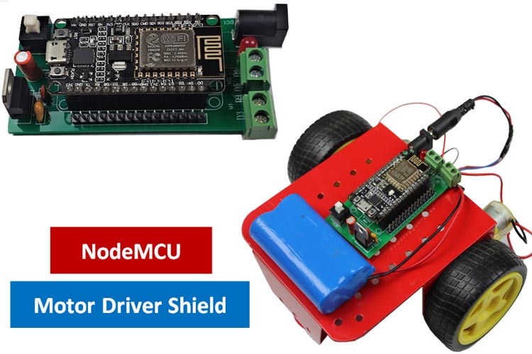
When developing robotic projects, motors are one of the most important parts of the whole project and there is always a need for multiple motors. But GPIO pins of the Microcontroller boards don’t allow you to draw the amount of current required for a motor. That’s why the motor driver ICs are used. You can build a motor driver circuit by using some electronic components or you can build an almost ready-to-go solution i.e. the Motor Driver Shield.
In this DIY tutorial, we are going to build a NodeMCU Motor Driver Shield to drive DC motors. This Motor Driver Shield consists of an L293D motor driver IC, a 6 pin switch to turn on/off the power, an LM7805 voltage regulator to get regulated 5V, and some extra pins for sensors, relay, etc. This Raspberry Pi HAT will come in handy while building a robotic project.
Here, we have used OurPCB to provide the PCB boards for this project. In the following sections of the article, we have covered in detail the complete procedure to design, order, and assemble the PCB boards for Raspberry pi Motor Driver HAT. We have also built Arduino Motor Driver Shield, Raspberry pi Lora HAT, and Raspberry Pi Motor Driver HAT in our previous projects.
Components Required for NodeMCU Motor Shield:
- NodeMCU
- L293D Motor Driver IC
- 7805 Voltage Regulator
- Capacitors (1×0.1µf, 1×0.33µf, 1×10µf)
- 1× 220 Ω Resistor
- 16 Pin IC Base
- 2× Screw Terminals
- 1× LED
- 1× DC Power Jack Female
Circuit Diagram for NodeMCU Motor Driver Shield
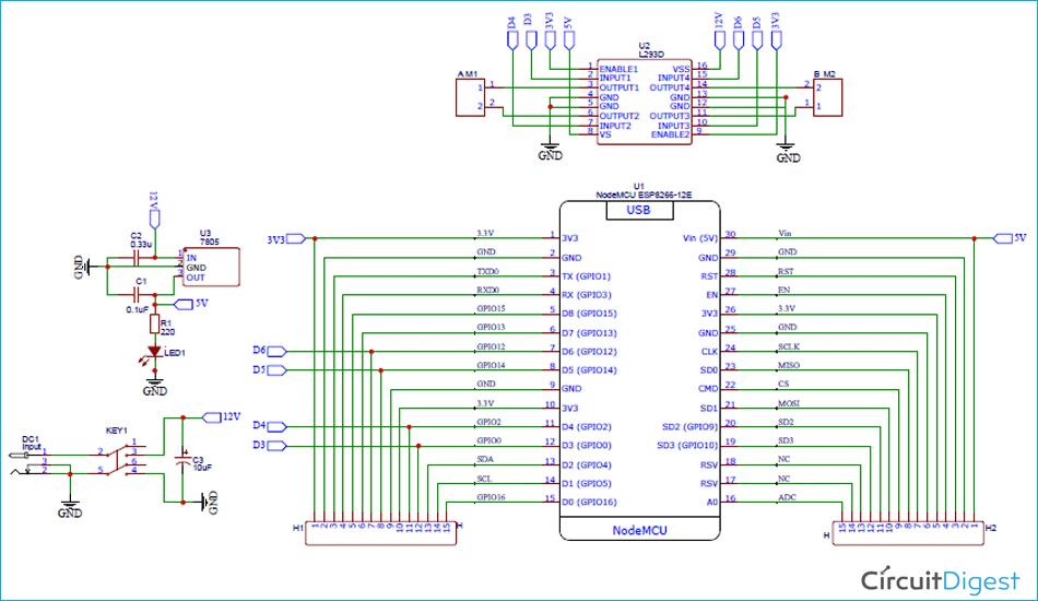
The complete schematic diagram for L293D Motor Driver Shield is shown below. The schematic was drawn using EasyEDA.
This Motor Driver Shield consists of an L293D Motor Driver IC, a 6 pin switch to turn on/off the power, and an LM7805 voltage regulator to get regulated 5V. It can control two DC motors. The NodeMCU digital pins D3 and D4 are connected to Left Motor and digital pins D5 and D6 are connected to Right Motor. In addition, this shield board has extra header pins for sensors, relays, or other devices.
Fabricating PCB for NodeMCU Motor Driver Shield
Once the schematic is done, we can proceed with laying out the PCB. You can design the PCB using any PCB software of your choice. We have used EasyEDA to fabricate PCB for this project. You can view any Layer (Top, Bottom, Topsilk, bottomsilk, etc.) of the PCB by selecting the layer from the ‘Layers’ window. Apart from this, you can get the 3D model view of the PCB on how it would appear after fabrication. Below are the 3D model views of the top layer and bottom layer of Pi Motor Driver HAT PCB.
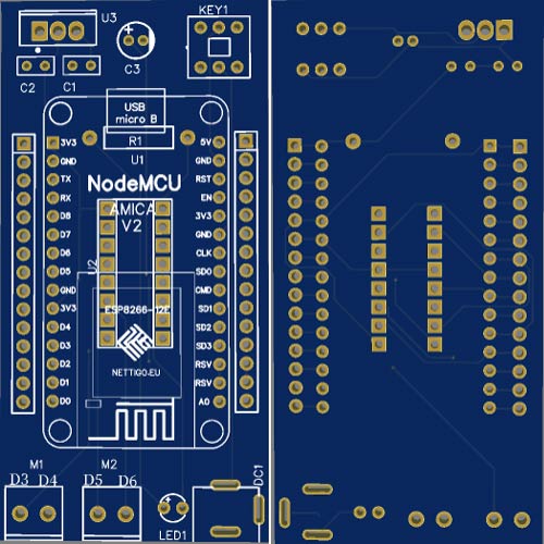
The PCB layout for the above circuit is also available for download as Gerber from the link given below:
Gerber file for NodeMCU Motor Shield
Ordering PCB from OurPCB
Once you are done with finalizing the design, you can proceed with ordering the PCB for which you need to follow the steps given below.
Step 1: Go to https://www.ourpcb.com/ and sign in. Sign up if this is your first time, and then scroll down. Click on ‘Quote Now’ in the PCB Manufacturing tab.

Step 2: You will be taken to a page where you will have to fill in a few details like the Name, Country, Phone Number, Specifications, and Gerber File. If you are opting for any specific parameters, you can list them here.
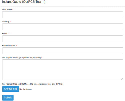
Step 3: That’s it, click on submit and you are done. OurPCB team will contact you through mail for further confirmation and payment.

Assembling the NodeMCU Motor Driver Shield PCB
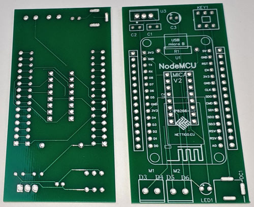
After a few days of ordering, we received our PCB in a neat package and the PCB quality was good as always. The top layer and the bottom layer of the board are shown below:
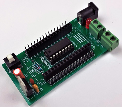
After making sure that the tracks and footprints were correct. I proceeded with assembling the PCB. The completely soldered board looked as shown in the image below:
NodeMCU Motor Driver Code Explanation
Here in this project, we are programming the NodeMCU to drive two DC motors in the Forward, Reverse, Left, and Right direction simultaneously in the two-second interval. Complete code is given at the end of the document. Here, we will be explaining some important parts of the code.
Start the code by defining the pins where the motor pins are connected. Here, I connected Input1 for motor A to D3, Input 2 to D4, Input1 for motor B to D5, and Input 2 to D6.
const int inputPin1  = D3;
const int inputPin2  = D4;
const int inputPin3  = D5;
const int inputPin4  = D6;
Inside the setup() function, define all four pins of motor A and motor B as outputs.
void setup()
{
    pinMode(inputPin1, OUTPUT);
    pinMode(inputPin2, OUTPUT);
    pinMode(inputPin3, OUTPUT);
    pinMode(inputPin4, OUTPUT);
}
Next, inside the loop() function drive two DC motors in the Forward, Reverse, Left, and Right direction simultaneously in the two-second interval. The table given below shows the input pins’ state combinations for the motor directions:
|
DIRECTION |
INPUT A1 |
INPUT A2 |
INPUT B1 |
INPUT B2 |
|---|---|---|---|---|
|
Forward |
1 |
0 |
1 |
0 |
|
Backward |
0 |
1 |
0 |
1 |
|
Right |
1 |
0 |
0 |
0 |
|
Left |
0 |
0 |
1 |
0 |
|
Stop |
0 |
0 |
0 |
0 |
void loop()
{
    //Forward
    digitalWrite(inputPin1, HIGH);
    digitalWrite(inputPin2, LOW);
    digitalWrite(inputPin3, HIGH);
    digitalWrite(inputPin4, LOW);
    delay(2000);
    //Left
    digitalWrite(inputPin1, LOW);
    digitalWrite(inputPin2, LOW);
    digitalWrite(inputPin3, HIGH);
    digitalWrite(inputPin4, LOW);
    delay(2000);
    //Right
    digitalWrite(inputPin1, HIGH);
    digitalWrite(inputPin2, LOW);
    digitalWrite(inputPin3, LOW);
    digitalWrite(inputPin4, LOW);
    delay(2000);
    //Reverse
    digitalWrite(inputPin1, LOW);
    digitalWrite(inputPin2, HIGH);
    digitalWrite(inputPin3, LOW);
    digitalWrite(inputPin4, HIGH);
    delay(2000);
    //Stop
    digitalWrite(inputPin1, LOW);
    digitalWrite(inputPin2, LOW);
    digitalWrite(inputPin3, LOW);
    digitalWrite(inputPin4, LOW);
    delay(2000);
}
Testing the NodeMCU Motor Driver Shield
Once you finish assembling the PCB, upload the code on NodeMCU and then mount the L293D IC and NodeMCU on the driver shield. If everything goes fine, the DC Motors connected to NodeMCU will move in the Left, Forward, Right, and Reverse direction simultaneously every two seconds.
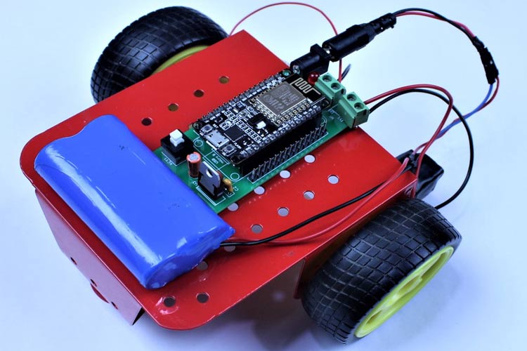
This is how you can build your own NodeMCU Motor Driver Shield. The complete code and working video of the project are given below. Hope you enjoyed the project and found it interesting to build your own. If you have any questions, please leave them in the comment section below.
//Motor A
const int inputPin1  = D3;
const int inputPin2  = D4;
//Motor B
const int inputPin3  = D5;
const int inputPin4  = D6;
void setup()
{
    pinMode(inputPin1, OUTPUT);
    pinMode(inputPin2, OUTPUT);
    pinMode(inputPin3, OUTPUT);
    pinMode(inputPin4, OUTPUT);
}
void loop()
{
    //Forward
    digitalWrite(inputPin1, HIGH);
    digitalWrite(inputPin2, LOW);
    digitalWrite(inputPin3, HIGH);
    digitalWrite(inputPin4, LOW);
    delay(2000);
    //Left
    digitalWrite(inputPin1, LOW);
    digitalWrite(inputPin2, LOW);
    digitalWrite(inputPin3, HIGH);
    digitalWrite(inputPin4, LOW);
    delay(2000);
    //Right
    digitalWrite(inputPin1, HIGH);
    digitalWrite(inputPin2, LOW);
    digitalWrite(inputPin3, LOW);
    digitalWrite(inputPin4, LOW);
    delay(2000);
    //Reverse
    digitalWrite(inputPin1, LOW);
    digitalWrite(inputPin2, HIGH);
    digitalWrite(inputPin3, LOW);
    digitalWrite(inputPin4, HIGH);
    delay(2000);
    //Stop
    digitalWrite(inputPin1, LOW);
    digitalWrite(inputPin2, LOW);
    digitalWrite(inputPin3, LOW);
    digitalWrite(inputPin4, LOW);
    delay(2000);
} 
