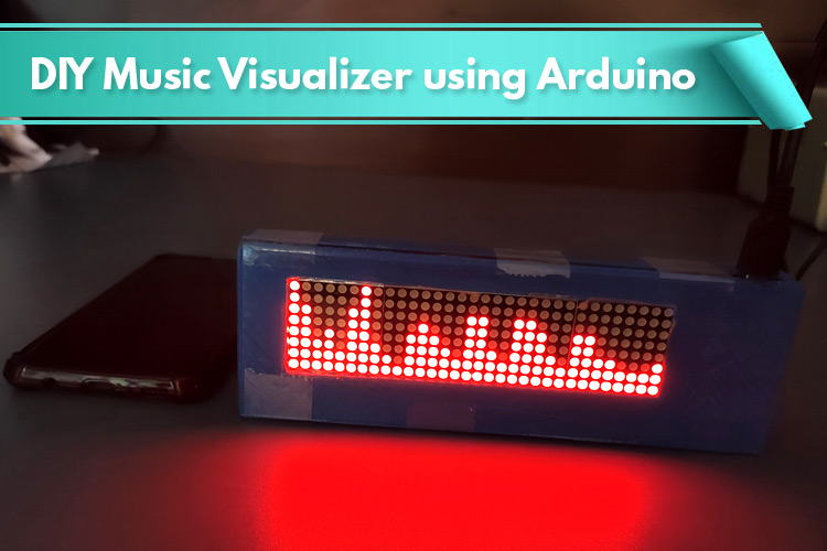
Most musical concerts nowadays are accompanied by some fancy light shows. Almost all concerts, festivals, and nightclubs have a visual show or effects to match. So, why not build your own music visualizer that reacts to the music or audio? Here's a simple yet effective project to make your very own music/audio visualizer using Arduino Nano, 32x8 Dot Matrix Display Module, and Audio Sensor. The LEDs on the 32x8 Dot Matrix Display will react according to the signals that Arduino receives through a microphone that is connected to its analog pin. Arduino has built-in ADC input audio signals received from the microphone to digital samples. Apart from this, we have also built some UV meter projects using Arduino and other microcontrollers.
Components Required for Building a Music/Audio Visualizer
To follow along with this tutorial, you'll need the following components:
- Arduino Nano
- MAX7219 32x8 Dot Matrix Display Module
- Microphone/Microphone Module
- Jumper Wires
- 3-D Printer (Optional)
What is MAX7219 32x8 Dot Matrix Display Module?
MAX7219 4-in-1 Display Dot Matrix Module is an integrated serial input/output common-cathode display designed to be mounted in a horizontal chain or to be expanded in a vertical plane to build a versatile display panel. This display module uses a convenient 3-wire serial interface to connect to all common controller boards like Arduino or Raspberry.
This display module contains four 8×8 dot matrix displays and four MAX7219 LED display driver ICs one for each display. An 8x8 LED matrix module contains 64 LED (Light Emitting Diodes) which are arranged in the form of a matrix; hence the name is LED matrix. If the module were to be drawn in the form of a circuit diagram, we will have a picture as shown below:
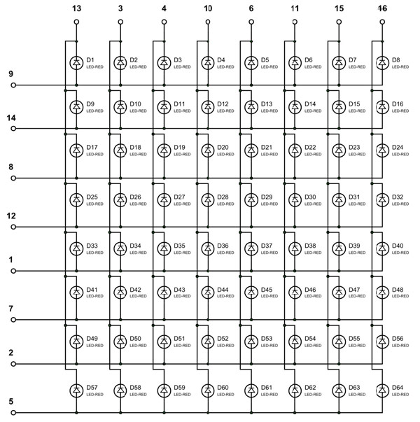
As shown in the above image, the 8×8 dot matrix display has 16 pins, 8 for each row and 8 for each column. Here, all the rows and columns are wired together to reduce the number of pins required. This technique of controlling a large number of LEDs with fewer pins is called Multiplexing. MAX7219 LED display driver ICs are used to control the display modules. This IC can precisely control and generate the pattern or text that you want. Apart from this, the other advantage of using this IC is that all the 64 LED can be controlled by just 3 pins.
Features & Specifications of MAX7219 32x8 Dot Matrix Display Module
- Input Voltage: 5V
- Max. Operating Current (mA): 320
- Requires only 3 communication wires of MCU
- Cascading multiple Matrix LED Module is very easy
- The size of the display is very compact
- The PCB features M3 holes for mounting
Audio Spectrum Visualizer Circuit Diagram
The complete schematic for interfacing 32x8 LED Matrix Display and Microphone with Arduino nano is shown in below image.
The Dot matrix display and Microphone both are powered with 5V and GND pins of Arduino Nano. But if you are planning to use the Dot matrix with its maximum brightness then it's better to use an external 5V source as the display draws a lot of current when set to maximum brightness. The data pin of the microphone is connected to the A7 pin of Arduino Nano. Now, we are left with SPI pins of the display. These pins are connected to hardware SPI pins of Arduino Nano as the hardware SPI pins are much faster than software SPI pins of any microcontroller.
The connections which are done between Arduino Nano, LED matrix module, and Microphone are shown in below table.
|
Arduino Nano |
32x8 LED Matrix |
|
5V |
VCC |
|
GND |
GND |
|
D11 |
DIN |
|
D10 |
CS |
|
D13 |
CLK |
|
Arduino Nano |
Microphone Module |
|
5V |
VCC |
|
GND |
GND |
|
A7 |
OUT |
|
|
|
Building the Circuit on Perf Board
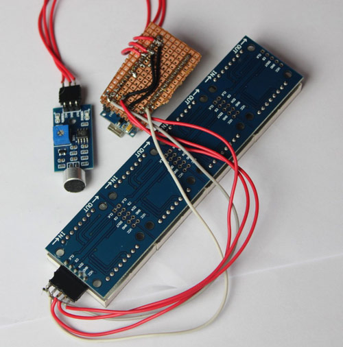
The idea is to fit this circuit inside a 3-D printed casing so that it can be mounted on a wall or placed beside the music system. For that, I soldered this complete circuit on a perf board. The perf board with all the soldered components is shown below:
Programming Arduino Nano Audio Visualization
Complete code for Audio Visualizer using Arduino is given at the end of the document. Here, we are explaining some important lines of the code. This code uses arduinoFFT.h and MD_MAX72xx.h libraries. Both the library can be installed from the Arduino IDE library manager. For that, open the Arduino IDE and go to Sketch < Include Library < Manage Libraries. Now, search for arduinoFFT and install the arduinoFFT library by Enrique Condes.

Similarly, install the MD_MAX72xx.h library by MajicDesigns.
After installing all the required libraries, start the code by including the libraries. ArduinoFFT library is used to translate the input analog signal into a frequency spectrum. MD_MAX72xx library is used to control the display and draw the audio spectrum on display. While the SPI library is used to establish SPI communication between Arduino and Dot-matrix display.
#include <arduinoFFT.h>
#include <MD_MAX72xx.h>
#include <SPI.h>
Next, create an instance for the MD_MAX72XX with the function MD_MAX72XX (). This function requires three parameters, the first being the hardware type, the second the CS pin, and the third, the maximum number of connected devices. Also, create an instance for arduinoFFT with the function arduinoFFT().
MD_MAX72XX disp = MD_MAX72XX(MD_MAX72XX::FC16_HW, 10, 4);
arduinoFFT FFT = arduinoFFT();
Then in the next lines, define two new arrays to store the 64-bit spectral components for the real and imaginary part of the spectrum.
double realComponent[64];
double imagComponent[64];
Now, inside the setup() function, initialize the Serial Monitor at a baud rate of 9600 for debugging purposes. Also, Initialize the Dot matrix display with the disp.begin() function.
void setup()
{
  disp.begin();
  Serial.begin(9600);
}
Now, within the loop function, we will take 64 samples of microphone readings using the for loop through the A7 pin of Arduino nano and store in into the ‘realComponent’ array that we defined earlier.
for (int i=0; i<64; i++)
  {
    realComponent[i] = analogRead(A7)/sensitivity;
    imagComponent[i] = 0;
  }
After getting the 64 spectral values from the microphone, we passed them through the FFT algorithm to compute the 64 spectral components for real and imaginary signals. Then in the next lines, we passed these reading FFT.ComplexToMagnitude() function to compute the magnitude of 64 spectral components.
FFT.Windowing(realComponent, 64, FFT_WIN_TYP_HAMMING, FFT_FORWARD);
FFT.Compute(realComponent, imagComponent, 64, FFT_FORWARD);
FFT.ComplexToMagnitude(realComponent, imagComponent, 64);
Now, in the next lines, we used a for loop to control all the 32 columns of the LED matrix. Inside this, for loop, we first converted these readings to a known range and then using the map function, we mapped these readings to a range from 0 to 8. Zero means all the LED of that particular column will be low and vice versa.
for(int i=0; i<32; i++)
  {
    realComponent[i] = constrain(realComponent[i],0,80);
    realComponent[i] = map(realComponent[i],0,80,0,8);
    index = realComponent[i];
    value = spectralHeight[index];
    c = 31 - i;
    disp.setColumn(c, value);
  }
3-D Printing the Casing for Audio Spectrum Visualizer
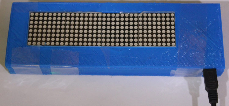
After soldering all the components on a perf board and programming the Arduino Nano, I printed a Casing for this circuit. For that, I measured the dimensions of the setup using my vernier to design a casing. My design looked something like this below once it was done. The STL file is also available for download from Thingiverse and you can print your casing using it.
Testing the Music Visualizer
Once the hardware and code were ready, we mounted the circuit inside the 3-D printed casing as shown below.
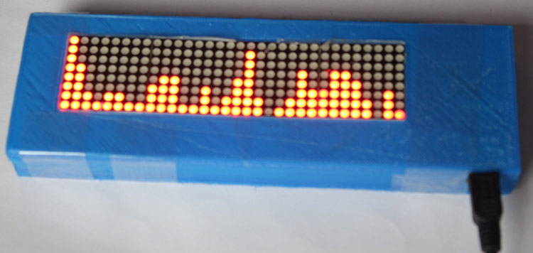
We used a 5V adapter to power the device. Initially, there will be nothing on display but when we play some music or speak in front of the mic then the LEDs of the dot matrix display changes according to the signal intensity.
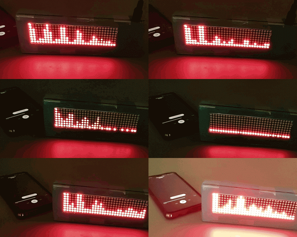
So, this is how you can use the Dot Matrix Display module with Arduino to build a music/Audio visualizer. Here, we used a microphone for sound input but you can also use the headphone out of the mobile/ music system if you want. If you have any questions regarding this project then post them in the comment section or use our forum to start a discussion on it.
#include <arduinoFFT.h>
#include <MD_MAX72xx.h>
#include <SPI.h>
MD_MAX72XX disp = MD_MAX72XX(MD_MAX72XX::FC16_HW, 10, 4);
arduinoFFT FFT = arduinoFFT();
double realComponent[64];
double imagComponent[64];
int spectralHeight[] = {0b00000000,0b10000000,0b11000000,
0b11100000,0b11110000,0b11111000,
0b11111100,0b11111110,0b11111111};
int index, c, value;
void setup()
{
disp.begin();
Serial.begin(9600);
}
void loop()
{
int sensitivity = map(analogRead(A6),0,1023,50,100);
Serial.println (analogRead(A6));
for(int i=0; i<64; i++)
{
realComponent[i] = analogRead(A7)/sensitivity;
imagComponent[i] = 0;
}
FFT.Windowing(realComponent, 64, FFT_WIN_TYP_HAMMING, FFT_FORWARD);
FFT.Compute(realComponent, imagComponent, 64, FFT_FORWARD);
FFT.ComplexToMagnitude(realComponent, imagComponent, 64);
for(int i=0; i<32; i++)
{
realComponent[i] = constrain(realComponent[i],0,80);
realComponent[i] = map(realComponent[i],0,80,0,8);
index = realComponent[i];
value = spectralHeight[index];
c = 31 - i;
disp.setColumn(c, value);
}
}


