In the last part, Designing Smartwatch using ESP32, we have looked at how to interface the BH1750 ambient light sensor and the MAX30102 Heart rate sensor for our smartwatch project. In this part, we will be looking at how to interface some other types of sensors to our smartwatch. So, here we will be interfacing the HMC5883L/QMC5883L Magnetometer sensor and the MPU6050 accelerometer gyroscope sensor. We will be looking at interfacing each of these modules separately.
Prerequisites – Installing Necessary Libraries
All the required libraries are provided in the GitHub repository given below the article. Download them and extract them to the library folder in the Arduino document folder. If you have already installed them, you don’t need to do the previous step except for the display library. For display, you must use the attached TFT_eSPI library. Once it’s done let’s move forward with the interface.
Required Libraries
Interfacing Magnetic Sensor
For the magnetic sensor, we are going to use the HMC5883L/QMC5883L. Since the sensor could indicate the geographic North, South, East, and West, we can use it as a digital compass. HMC5883L/QMC5883L has 3 magneto-resistive materials inside, which are arranged in the axes x, y, and z. The amount of current flowing through these materials is sensitive to the earth’s magnetic field. So, by measuring the change in current flowing through these materials we can detect the change in Earth’s magnetic field. Once the change in the magnetic field is absorbed, the values can then be sent to any embedded controller like a microcontroller or processor through the I2C protocol.
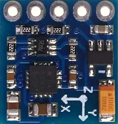
HMC5883L/QMC5883L Module Pinout
The HMC5883L/QMC5883L module has a total of 5 pins. All the pins of this sensor module are digital, except VCC and Ground. In which 4 pins are used for interfacing with the MCU and one optional interrupt pin. The pinout of the HMC5883L/QMC5883L module is as follows:
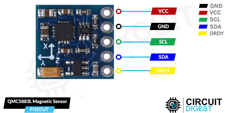
GND Ground connection for the module. Connect to the GND pin of the ESP32.
VCC Provides power for the module. Connect to the 3.3V pin of the ESP32.
SCL Serial Clock pin. Used for providing clock pulse for I2C Communication.
SDA Serial Data pin. Used for transferring Data through I2C communication.
DRDY When the output value of the sensor is ready, an interrupt occurs in this pin. This pin is pulled up inside the module by default. When the output value of the module is ready, the pin is set to “0” for 250 microseconds.
Circuit Diagram to Interface Magnetic sensor with ESP32
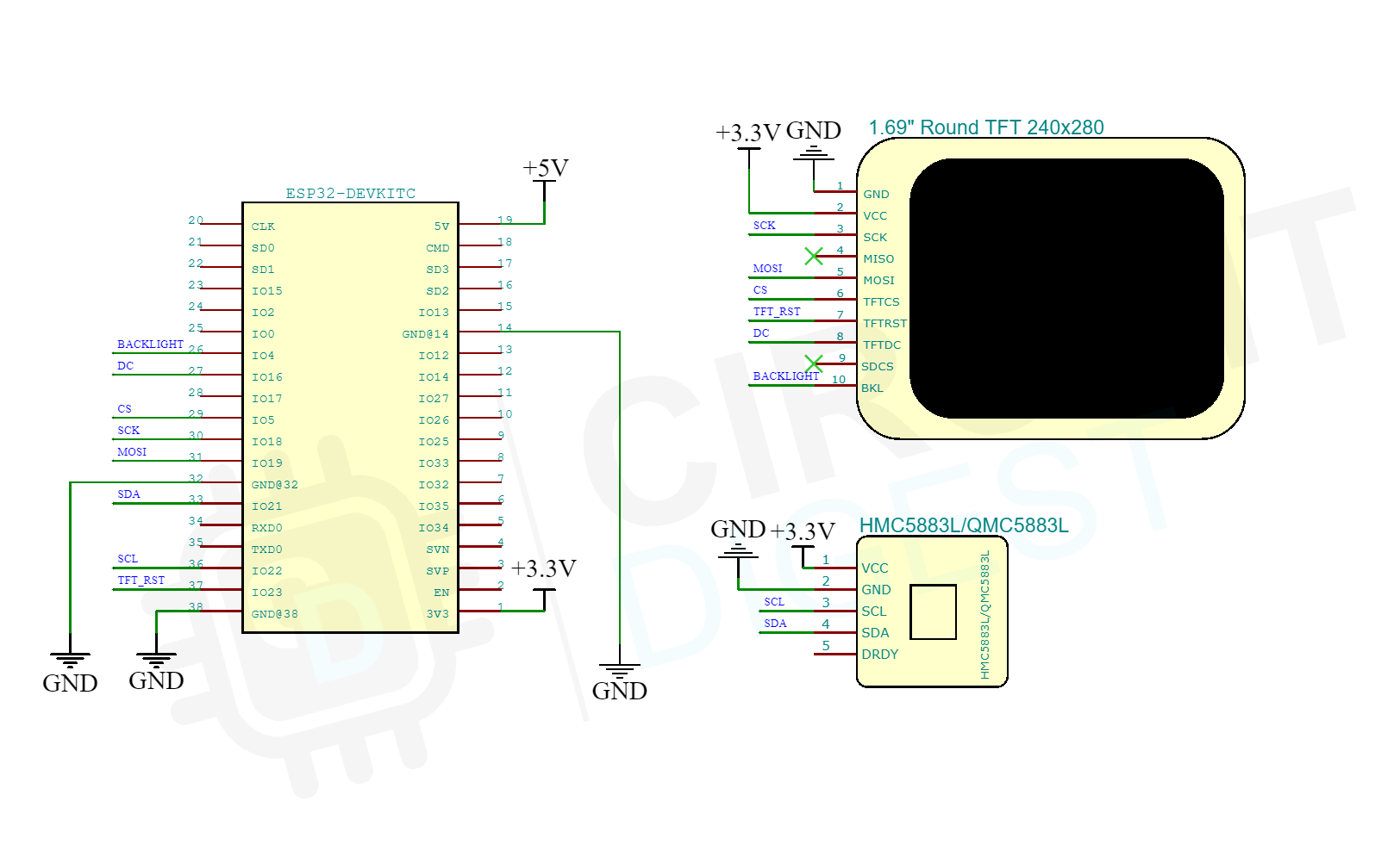
For testing, connect the Magnetic sensor module along with the display module to the ESP32 Devkit as per the Circuit diagram below. Connect the sensor to the I2C line and the display to the SPI bus as before.
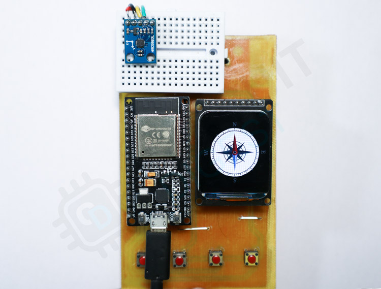
Here is the actual setup. The QMC5883L module is connected to the ESP32 through I2C lines.
Testing Sensor
Once all the connections are done as per the schematics, download the QMC5883L demo code and the relevant libraries from GitHub. Extract the libraries to the Arduino library folder and extract the code to any folder and open it using the Arduino IDE. Select ESP32 Devkit as the board and compile the code. Once the code is compiled, upload it to the ESP32. The display will show a digital compass. You can observe that the compass is showing the correct direction and will keep it that way as long as there is no magnetic interference. While testing, make sure that there is no magnetic materials or magnetic field near the sensor. Otherwise, it may affect the readings. The below video will demonstrate the same.
Code explanation
In the code, we have used the TFT_eSPI and DFRobot_QMC5883 libraries. The DFRobot QMC5883 library supports both HMC5883L and QMC5883L chips. Because both of these sensors have different I2C addresses and different internal register mapping, we will set the corresponding configuration based on the chip address we have received after initializing the library. Once it’s done, we will read the corresponding register for the reading from each axis and will calculate the heading from it. For the accurate calculation, we have to change the declination angle as per our location. You can find the instructions for the same in the code itself.
Once the heading is calculated, we will load the compass dial image to the sprite we have created in the memory. Then the sprite is pushed to the display at an angle. For this, we have used the pushRotated function from the TFT_eSPI library. This function will rotate the image which is pushed to the display as per the angle we have calculated from the QMC5883L. This will give us a smooth display with an accurate digital compass pointing to the north. For accuracy, make sure to fix the sensor in the correct orientation, away from any magnetic material. Keep in mind that even the contacts in the breadboard can affect the sensor.
Interfacing Accelerometer Gyroscope sensor
For the accelerometer gyroscope sensor, we have selected the popular MPU6050 sensor. It is very popular among the DIY Community because it is very cheap and easy to interface with. We will use this sensor for detecting motion and to enable features like rise to wake up. Let’s look at the specifications of the sensor itself.
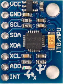
The MPU6050 is a very popular accelerometer gyroscope chip that has six axes sense with a 16-bit measurement resolution. This high accuracy in sense and the cheap cost make it very popular among the DIY community. Even many commercial products are equipped with the MPU6050. The combination of gyroscope and accelerometers is commonly referred to as an Inertial Measurement Unit or IMU.
IMU sensors are used in a wide variety of applications such as mobile phones, tablets, satellites, spacecraft, drones, UAVs, robotics, and many more. They are used for motion tracking, orientation and position detection, flight control, etc.
MPU6050 Module Pinout
The MPU6050 module has a total of 8 pins. In which at least 4 pins are necessary for the interfacing. The pinout of the MPU6050 module is as follows:
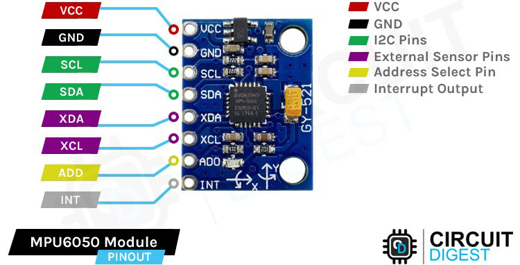
GND Ground connection for the module. Connect to the GND pin of the ESP32.
VCC Provides power for the module. Connect to the 3.3V pin of the ESP32.
SCL Serial Clock pin. Used for providing clock pulse for I2C Communication.
SDA Serial Data pin. Used for transferring Data through I2C communication.
XDA Auxiliary Serial Data - Can be used to interface other I2C modules with MPU6050.
XCL Auxiliary Serial Clock - Can be used to interface other I2C modules with MPU6050.
ADD/AD0 Address select pin if multiple MPU6050 modules are used.
INT Interrupt pin to indicate that data is available for MCU to read.
Circuit Diagram to Interface Accelerometer Gyroscope sensor with ESP32
For testing, connect the accelerometer gyroscope sensor module along with the display module to the ESP32 Devkit as per the Circuit diagram below. Connect the sensor to the I2C line and the display to the SPI bus as before.
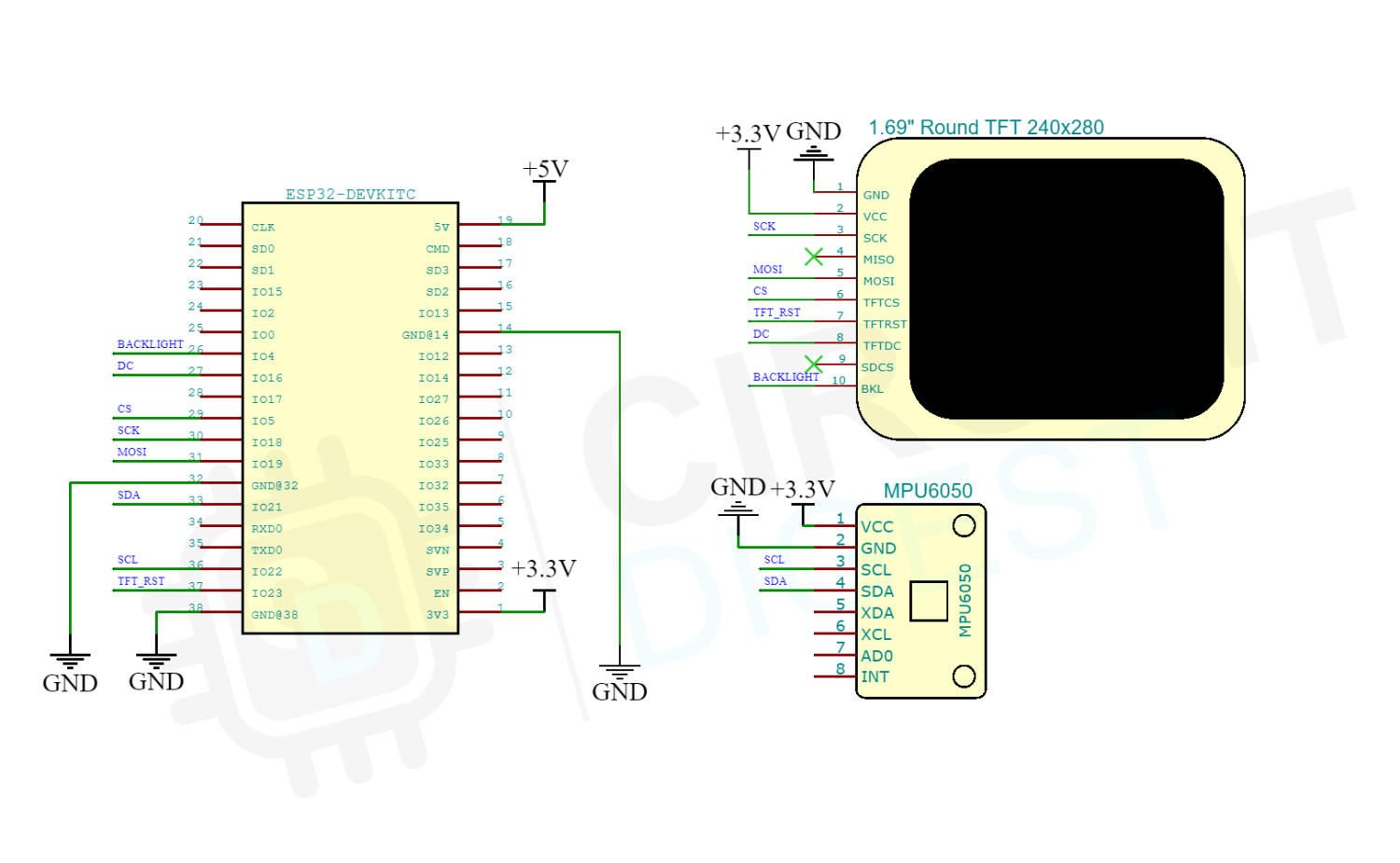
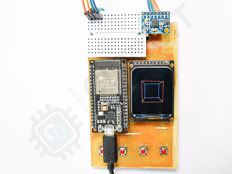
Here is the actual setup. The MPU6050 module is connected using the jumper cable, to get the flexibility to move the module during the test.
Testing Sensor
Once all the connections are done as per the schematics, download the MPU6050 demo code from GitHub. Extract it to a folder and open it using the Arduino IDE. Select ESP32 Devkit as the board and compile the code. Once the code is compiled, upload it to the ESP32. The display will show a 3D cube. You can rotate the cube by rotating the MPU6050 module. The ESP32 will read Gyroscope data from MPU6050 and will process the 3D cube as per those values. The below video will demonstrate the same.
Code Explanations
In the code, we have created a 3D cube with a total of 12 lines. The cube will rotate as per the reading from the gyroscope sensor. You can rotate the cube by rotating the MPU6050 module. The ESP32 will read Gyroscope data from MPU6050 and will process data to calculate the coordinates of each line that is used to create the 3D.
For reading the values from the MPU6050, we haven’t used any specific library. Instead, we have read those values directly from the MPU6050 registers through I2C with Wire.read function. We will read a total of 14 registers which will have the x,y, and z data from the accelerometer and gyroscope.
You can download all the required files including the libraries from the Circuit Digest GitHub Repo.
#define BLACK 0x0000
#define WHITE 0xFFFF

#include <Wire.h>
#include <SPI.h>

#include <TFT_eSPI.h> // Hardware-specific library
#include "Free_Fonts.h"
TFT_eSPI tft = TFT_eSPI();       // Invoke custom library
//MPU
const int MPU = 0x68; // I2C address of the MPU-6050
int16_t AcX, AcY, AcZ, Tmp, GyX, GyY, GyZ;
int16_t h;
int16_t w;

int inc = -2;

float xx, xy, xz;
float yx, yy, yz;
float zx, zy, zz;

float fact;

int Xan, Yan;

int Xoff;
int Yoff;
int Zoff;

struct Point3d
{
  int x;
  int y;
  int z;
};

struct Point2d
{
  int x;
  int y;
};

int LinestoRender; // lines to render.
int OldLinestoRender; // lines to render just in case it changes. this makes sure the old lines all get erased.

struct Line3d
{
  Point3d p0;
  Point3d p1;
};

struct Line2d
{
  Point2d p0;
  Point2d p1;
};

Line3d Lines[20];
Line2d Render[20];
Line2d ORender[20];

/***********************************************************************************************************************************/
void setup() {
  Wire.begin();
  tft.init();

  h = tft.height();
  w = tft.width();

  tft.setRotation(0);

  tft.fillScreen(TFT_BLACK);

  cube();

  fact = 180 / 3.14159259; // conversion from degrees to radians.

  Xoff = 120; // Position the centre of the 3d conversion space into the centre of the TFT screen.
  Yoff = 140;
  Zoff = 550; // Z offset in 3D space (smaller = closer and bigger rendering)

  // Initialize MPU
  Wire.beginTransmission(MPU);
  Wire.write(0x6B);  // PWR_MGMT_1 register
  Wire.write(0);     // set to zero (wakes up the MPU-6050)
  Wire.endTransmission(true);
}

/***********************************************************************************************************************************/
void loop() {
  //For cube rotation
  int xOut = 0;
  int yOut = 0;
  // Rotate around x and y axes in 1 degree increments
  xOut = map(AcX, -17000, 17000, -50, 50);
  yOut = map(AcY, -17000, 17000, -50, 50);
  Xan = xOut;
  Yan = yOut;
  Yan = Yan % 360;
  Xan = Xan % 360; // prevents overflow.

  SetVars(); //sets up the global vars to do the 3D conversion.
  Zoff = 240;
  /*
    // Zoom in and out on Z axis within limits
    // the cube intersects with the screen for values < 160
    Zoff += inc;
    if (Zoff > 500) inc = -1;     // Switch to zoom in
    else if (Zoff < 160) inc = 1; // Switch to zoom out
  */
  for (int i = 0; i < LinestoRender ; i++)
  {
    ORender[i] = Render[i]; // stores the old line segment so we can delete it later.
    ProcessLine(&Render[i], Lines[i]); // converts the 3d line segments to 2d.
  }
  RenderImage(); // go draw it!

  delay(14); // Delay to reduce loop rate (reduces flicker caused by aliasing with TFT screen refresh rate)
}

/***********************************************************************************************************************************/
void RenderImage( void)
{
  // renders all the lines after erasing the old ones.
  // in here is the only code actually interfacing with the OLED. so if you use a different lib, this is where to change it.

  for (int i = 0; i < OldLinestoRender; i++ )
  {
    tft.drawLine(ORender[i].p0.x, ORender[i].p0.y, ORender[i].p1.x, ORender[i].p1.y, BLACK); // erase the old lines.
  }


  for (int i = 0; i < LinestoRender; i++ )
  {
    uint16_t color = TFT_BLUE;
    if (i < 4) color = TFT_RED;
    if (i > 7) color = TFT_GREEN;
    tft.drawLine(Render[i].p0.x, Render[i].p0.y, Render[i].p1.x, Render[i].p1.y, color);
  }
  OldLinestoRender = LinestoRender;


  Wire.beginTransmission(MPU);
  Wire.write(0x3B);  // starting with register 0x3B (ACCEL_XOUT_H)
  Wire.endTransmission(true);
  Wire.requestFrom(MPU, 14, true); // request a total of 14 registers
  AcX = Wire.read() << 8 | Wire.read(); // 0x3B (ACCEL_XOUT_H) & 0x3C (ACCEL_XOUT_L)
  AcY = Wire.read() << 8 | Wire.read(); // 0x3D (ACCEL_YOUT_H) & 0x3E (ACCEL_YOUT_L)
  AcZ = Wire.read() << 8 | Wire.read(); // 0x3F (ACCEL_ZOUT_H) & 0x40 (ACCEL_ZOUT_L)
  Tmp = Wire.read() << 8 | Wire.read(); // 0x41 (TEMP_OUT_H) & 0x42 (TEMP_OUT_L)
  GyX = Wire.read() << 8 | Wire.read(); // 0x43 (GYRO_XOUT_H) & 0x44 (GYRO_XOUT_L)
  GyY = Wire.read() << 8 | Wire.read(); // 0x45 (GYRO_YOUT_H) & 0x46 (GYRO_YOUT_L)
  GyZ = Wire.read() << 8 | Wire.read(); // 0x47 (GYRO_ZOUT_H) & 0x48 (GYRO_ZOUT_L)
}

/***********************************************************************************************************************************/
// Sets the global vars for the 3d transform. Any points sent through "process" will be transformed using these figures.
// only needs to be called if Xan or Yan are changed.
void SetVars(void)
{
  float Xan2, Yan2, Zan2;
  float s1, s2, s3, c1, c2, c3;

  Xan2 = Xan / fact; // convert degrees to radians.
  Yan2 = Yan / fact;

  // Zan is assumed to be zero

  s1 = sin(Yan2);
  s2 = sin(Xan2);

  c1 = cos(Yan2);
  c2 = cos(Xan2);

  xx = c1;
  xy = 0;
  xz = -s1;

  yx = (s1 * s2);
  yy = c2;
  yz = (c1 * s2);

  zx = (s1 * c2);
  zy = -s2;
  zz = (c1 * c2);
}


/***********************************************************************************************************************************/
// processes x1,y1,z1 and returns rx1,ry1 transformed by the variables set in SetVars()
// fairly heavy on floating point here.
// uses a bunch of global vars. Could be rewritten with a struct but not worth the effort.
void ProcessLine(struct Line2d *ret, struct Line3d vec)
{
  float zvt1;
  int xv1, yv1, zv1;

  float zvt2;
  int xv2, yv2, zv2;

  int rx1, ry1;
  int rx2, ry2;

  int x1;
  int y1;
  int z1;

  int x2;
  int y2;
  int z2;

  int Ok;

  x1 = vec.p0.x;
  y1 = vec.p0.y;
  z1 = vec.p0.z;

  x2 = vec.p1.x;
  y2 = vec.p1.y;
  z2 = vec.p1.z;

  Ok = 0; // defaults to not OK

  xv1 = (x1 * xx) + (y1 * xy) + (z1 * xz);
  yv1 = (x1 * yx) + (y1 * yy) + (z1 * yz);
  zv1 = (x1 * zx) + (y1 * zy) + (z1 * zz);

  zvt1 = zv1 - Zoff;

  if ( zvt1 < -5) {
    rx1 = 256 * (xv1 / zvt1) + Xoff;
    ry1 = 256 * (yv1 / zvt1) + Yoff;
    Ok = 1; // ok we are alright for point 1.
  }

  xv2 = (x2 * xx) + (y2 * xy) + (z2 * xz);
  yv2 = (x2 * yx) + (y2 * yy) + (z2 * yz);
  zv2 = (x2 * zx) + (y2 * zy) + (z2 * zz);

  zvt2 = zv2 - Zoff;

  if ( zvt2 < -5) {
    rx2 = 256 * (xv2 / zvt2) + Xoff;
    ry2 = 256 * (yv2 / zvt2) + Yoff;
  } else
  {
    Ok = 0;
  }

  if (Ok == 1) {

    ret->p0.x = rx1;
    ret->p0.y = ry1;

    ret->p1.x = rx2;
    ret->p1.y = ry2;
  }
  // The ifs here are checks for out of bounds. needs a bit more code here to "safe" lines that will be way out of whack, so they don't get drawn and cause screen garbage.

}

/***********************************************************************************************************************************/
// line segments to draw a cube. basically p0 to p1. p1 to p2. p2 to p3 so on.
void cube(void)
{
  // Front Face.

  Lines[0].p0.x = -50;
  Lines[0].p0.y = -50;
  Lines[0].p0.z = 50;
  Lines[0].p1.x = 50;
  Lines[0].p1.y = -50;
  Lines[0].p1.z = 50;

  Lines[1].p0.x = 50;
  Lines[1].p0.y = -50;
  Lines[1].p0.z = 50;
  Lines[1].p1.x = 50;
  Lines[1].p1.y = 50;
  Lines[1].p1.z = 50;

  Lines[2].p0.x = 50;
  Lines[2].p0.y = 50;
  Lines[2].p0.z = 50;
  Lines[2].p1.x = -50;
  Lines[2].p1.y = 50;
  Lines[2].p1.z = 50;

  Lines[3].p0.x = -50;
  Lines[3].p0.y = 50;
  Lines[3].p0.z = 50;
  Lines[3].p1.x = -50;
  Lines[3].p1.y = -50;
  Lines[3].p1.z = 50;


  //back face.

  Lines[4].p0.x = -50;
  Lines[4].p0.y = -50;
  Lines[4].p0.z = -50;
  Lines[4].p1.x = 50;
  Lines[4].p1.y = -50;
  Lines[4].p1.z = -50;

  Lines[5].p0.x = 50;
  Lines[5].p0.y = -50;
  Lines[5].p0.z = -50;
  Lines[5].p1.x = 50;
  Lines[5].p1.y = 50;
  Lines[5].p1.z = -50;

  Lines[6].p0.x = 50;
  Lines[6].p0.y = 50;
  Lines[6].p0.z = -50;
  Lines[6].p1.x = -50;
  Lines[6].p1.y = 50;
  Lines[6].p1.z = -50;

  Lines[7].p0.x = -50;
  Lines[7].p0.y = 50;
  Lines[7].p0.z = -50;
  Lines[7].p1.x = -50;
  Lines[7].p1.y = -50;
  Lines[7].p1.z = -50;


  // now the 4 edge lines.

  Lines[8].p0.x = -50;
  Lines[8].p0.y = -50;
  Lines[8].p0.z = 50;
  Lines[8].p1.x = -50;
  Lines[8].p1.y = -50;
  Lines[8].p1.z = -50;

  Lines[9].p0.x = 50;
  Lines[9].p0.y = -50;
  Lines[9].p0.z = 50;
  Lines[9].p1.x = 50;
  Lines[9].p1.y = -50;
  Lines[9].p1.z = -50;

  Lines[10].p0.x = -50;
  Lines[10].p0.y = 50;
  Lines[10].p0.z = 50;
  Lines[10].p1.x = -50;
  Lines[10].p1.y = 50;
  Lines[10].p1.z = -50;

  Lines[11].p0.x = 50;
  Lines[11].p0.y = 50;
  Lines[11].p0.z = 50;
  Lines[11].p1.x = 50;
  Lines[11].p1.y = 50;
  Lines[11].p1.z = -50;

  LinestoRender = 12;
  OldLinestoRender = LinestoRender;

}
#include <SPI.h>
#include <Wire.h>
#include <TFT_eSPI.h> // Modified library for ST7789 Display
#include <DFRobot_QMC5883.h>
#include "dial240.h" //Image data
#define TFT_GREY 0x5AEB
#define TFT_SKYBLUE 0x067D
#define color1 TFT_WHITE
#define color2  0x8410//0x8410
#define color3 0x5ACB
#define color4 0x15B3
#define color5 0x00A3
#define background 0x65B8
TFT_eSPI tft = TFT_eSPI();       // TFT_eSPI Instance
TFT_eSprite img = TFT_eSprite(&tft);   //Create sprite for faster updation
DFRobot_QMC5883 compass;
int angle = 0;
bool cw = true;
void setup(void) {
  Serial.begin(115200);
  compass.begin();
    if(compass.isHMC()){
        Serial.println("Initialize HMC5883");
        compass.setRange(HMC5883L_RANGE_1_3GA);
        compass.setMeasurementMode(HMC5883L_CONTINOUS);
        compass.setDataRate(HMC5883L_DATARATE_15HZ);
        compass.setSamples(HMC5883L_SAMPLES_8);
    }
   else if(compass.isQMC()){
        Serial.println("Initialize QMC5883");
        compass.setRange(QMC5883_RANGE_2GA);
        compass.setMeasurementMode(QMC5883_CONTINOUS);
        compass.setDataRate(QMC5883_DATARATE_50HZ);
        compass.setSamples(QMC5883_SAMPLES_8);
   }
  tft.init();
  tft.setRotation(0);
  tft.setSwapBytes(true);
  tft.fillScreen(TFT_BLACK);
  int xw = tft.width()/2;   // xw, yh is middle of screen
  int yh = tft.height()/2;
  tft.setPivot(xw, yh);     // Set pivot to middle of TFT screen
  //img.setColorDepth(8);
  img.createSprite(240, 240);
  img.setTextDatum(4);
}

void loop() {
  Vector norm = compass.readNormalize();

  // Calculate heading
  float heading = atan2(norm.YAxis, norm.XAxis);

  // Set declination angle on your location and fix heading
  // You can find your declination on: http://magnetic-declination.com/
  // (+) Positive or (-) for negative
  // For my location declination angle is -1'22W (negative)
  // Formula: (deg + (min / 60.0)) / (180 / M_PI);
  float declinationAngle = (-1.0 + (-22.0 / 60.0)) / (180 / PI);
  heading += declinationAngle;

  // Correct for heading < 0deg and heading > 360deg
  if (heading < 0){
    heading += 2 * PI;
  }

  if (heading > 2 * PI){
    heading -= 2 * PI;
  }

  // Convert to degrees
  float headingDegrees = heading * 180/M_PI;
  img.fillSprite(TFT_BLACK);
  img.pushImage(0, 0, 240, 240, dial240);
  img.pushRotated(angle,TFT_PINK);// create rotated image as per the angle from the compass sensor
  delay(14);
}
