The need for home security alarm systems nowadays is a serious demand. As the number of crimes is increasing every day, there has to be something that will keep us safe. A motion sensor dog barking alarm can be a great choice for that purpose. The sound will alert you when someone approaches the house. They can also deter burglars from deciding to enter a home.
So in this tutorial, we are going to build a Dog Barking Security Alarm using Arduino Nano, PIR Motion Sensor, and Dog Barking Sound Module. When someone gets close to your house door, a barking dog alarm will be triggered from inside the house, making all undesirable guests go away. We have already built many home security projects, using different microcontrollers and sensors; you can also check them for more inspiration.
Components Required for Dog Barking Security Alarm
- Arduino Nano
- PIR Motion Sensor
- Dog Barking Sound Module
- LM386 Amplifier Module
- 8ohm (0.25W to 2W) Speaker
- Capacitor (220uF, 2×10uF, 2×0.1uF)
- Resistor (2×10kΩ)
- 100k Potentiometer
Dog Barking Sound Module
A useful, as well as a single module to produce dog barking sound, can be easily interfaced with speakers and a simple power supply without the need for additional amplifiers and passive components. The module comes with a non-removable chip and easy-to-connect PCB leads for trouble-free soldering. It can be powered using 3-4.5V DC. The output specification requires an 8 Ohms speaker with 0.25W to 2W sound output. Inbuilt button or trigger offers one-time play (three-time dog bark) if shorted.
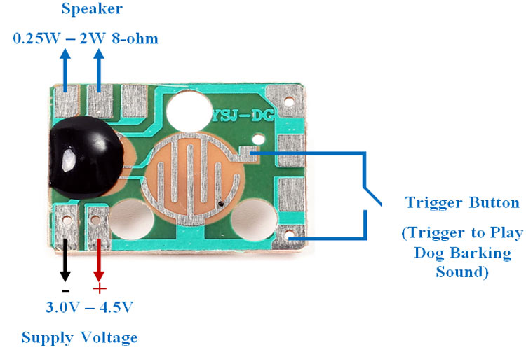
Dog Barking Music Chip Features & Specifications:
- Good Quality Output
- 3.0-4.5V Operation voltage
- No additional amplifier requires
- Small size PCB to be fitted in very small space during DIY
- 0.25W-2W speaker support with 8 Ohms impedance
- Solder-able pads available in the module
Dog Barking Security Alarm Circuit Diagram
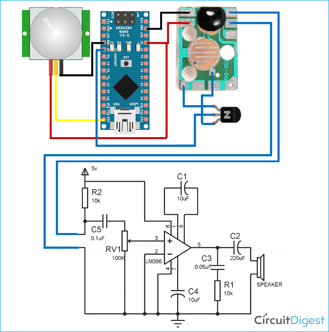
The schematic for the Dog Barking Alarm using Arduino is given below. The Amplifier IC is used to amplify the Output from Dog Barking Sound Module.
The Alarm circuit consists of an Arduino Nano, PIR Motion sensor, LM386 Amplifier IC, Speaker, NPN Transistor, and a couple of resistors and capacitors. BC547 Transistor is used to activate the Alarm whenever PIR Sensor detects motion. The VCC and GND pins of the PIR Sensor are connected to 5V and GND of Arduino, while the OUT pin is connected to digital pin 12 of Arduino.
Pin 1 and Pin 8 of the Amplifier IC are the gain control pins, internally the gain is set to 20 but it can be increased up to 200 by using a capacitor between PIN 1 and 8. We have used 10uF capacitor C1 to get the highest gain i.e. 200.
Pin 2 and Pin 3 are the input PINs. Pin 2 is the negative input terminal, connected to the ground. Pin 3 is the positive input terminal, in which the sound signal is fed to be amplified. In our circuit, it is connected to the one terminal of the Dog Barking Module with a 100k potentiometer RV1.
Pin 4 and Pin 6 are the power supply Pins of IC, Pin 6 for is +Vcc and Pin 4 is Ground. The circuit can be powered with a voltage between 5-12v.
Pin 5 is the output PIN from which we get the amplified sound signal. The output signal has both AC and DC components. DC component is undesirable and can’t be fed to Speaker. So to remove this DC component, a capacitor of 220uF has been used.
Pin 7 is the bypass terminal. It can be left open or can be grounded using a capacitor for stability.
Building the Circuit on Perf Board
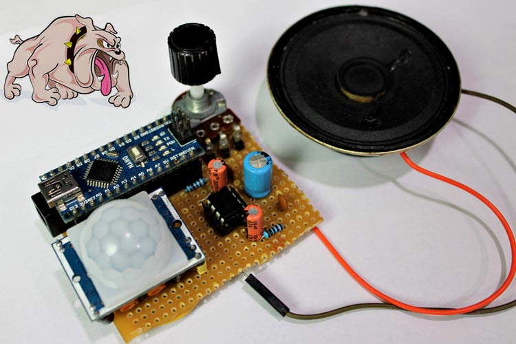
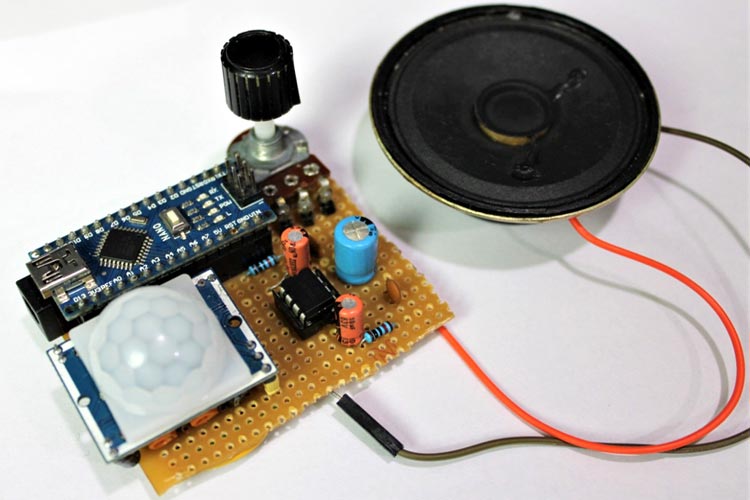
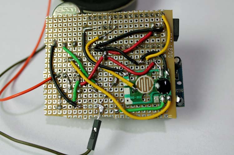
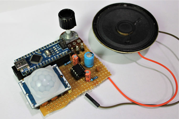
The complete circuit shown above is soldered onto a perf board. Make sure to use wires to leave enough distance to mount the Arduino and Sensors. I have soldered the Dog Barking sound module on the backside of the perf board. My perf board soldered to Arduino and the sensor module is shown below.
Programming Arduino for Burglar Alarm
The code for Dog Barking Alarm using Arduino and PIR Sensor is very simple. Complete code can be found at the end of the document. The explanation of the code is as follows:
Start the code by defining all the necessary pins that are required to read the sensor data and control the transistor.
int Sensor = 12;
int transistor = 2;
Then inside the setup() function, initialize the serial monitor at 9600 for debugging purposes. Also, set the sensor pin as input and the transistor pin as output.
void setup() {
  Serial.begin(9600);
  pinMode (Sensor, INPUT);
  pinMode (transistor, OUTPUT);
  Serial.println("Waiting for motion");}
Then inside the loop() function, read the sensor pin using digitalRead() and if the pin is valued greater than 0, then turn on the Alarm else turn off the Alarm.
void loop() {
     int val = digitalRead(Sensor);
     if(val ==HIGH)
     {
        digitalWrite(transistor, HIGH);
        Serial.println("Motion Detected");
     }
     if(val == LOW)
     {
        digitalWrite(transistor, LOW);
        Serial.println("NO Motion");
     }
     delay(1000);
}
Working of Dog Barking Security using Arduino
Make the connections as per the circuit diagram and upload the code to Arduino Nano. When powered, the PIR sensor detects the IR rays emitted from the human body. When any human is detected, the PIR sensor outputs a logic HIGH value i.e. voltage of 3.5V to 5V to Arduino’s digital pin 12. As soon as the Arduino detects logic HIGH on Pin 12, it switches the transistor, and the alarm is activated. In this circuit, it produces Dog Bark sound three times.
The complete working of the project can be found in the video given below; if you have any questions, feel free to write them in the comment section below.
int Sensor = 12;
int transistor = 2;
void setup() {
Serial.begin(9600);
pinMode (Sensor, INPUT);
pinMode (transistor, OUTPUT);
Serial.println("Waiting for motion");}
void loop() {
int val = digitalRead(Sensor);
if(val ==HIGH)
{
digitalWrite(transistor, HIGH);
Serial.println("Motion Detected");
}
if(val == LOW)
{
digitalWrite(transistor, LOW);
Serial.println("NO Motion");
}
delay(1000);
}

