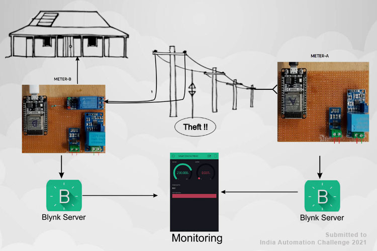
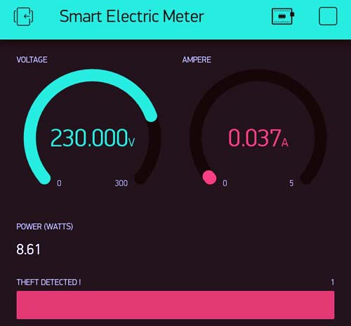
The ESP32 based project is basically to detect the theft from the energy meter used in households as well as in the commercial sector. There is two based meter one for the distribution line and one for the consumer side. Whenever the distribution line load reading does not match the consumer side reading; that means there is some kind of power leakage in between distribution and consumer line, leading to deference in energy readings, and theft will be detected. When the theft will occur, a notification will be sent to the app and consumer side power will be cut off. The data send to the Blynk Application Dashboard and display's the Voltage, Current, Power & total unit consumed in kWh with theft detection alert.
Component Requirement for Smart Electricity Meter
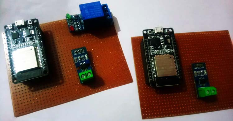
Project Used Hardware
- ESP32,
- ACS712 current sensor module,
- ZMPT101B voltage sensor module,
- Relay module,
- Connection Wires
Project Used Software
- Arduino,
- Blynk IoT platform
Project Hardware Software Selection
I need to select the current sensor as well as the voltage sensor so that the current & voltage can be measured and thus I can know about the power consumption & total power consumed for theft detection with the help of ESP32 and IoT Blynk platform.
ESP32: ESP32 microcontroller module offers a built-in Wi-Fi feature which is ideal for IoT projects since the project is based on the same.
ZMPT101B: ZMPT101B is a high-precision voltage Transformer I use to measure the accurate AC voltage.
ACS712: ACS712 is a fully integrated, hall effect-based linear current sensor used to measure the alternating current in this project.
Relay Module: The relay module is used as a switch for the main power line. It is controlled by ESP32, when theft is detected, the relay activates and cuts the mains power.
Circuit Diagram
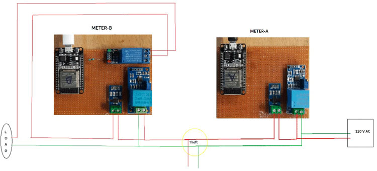
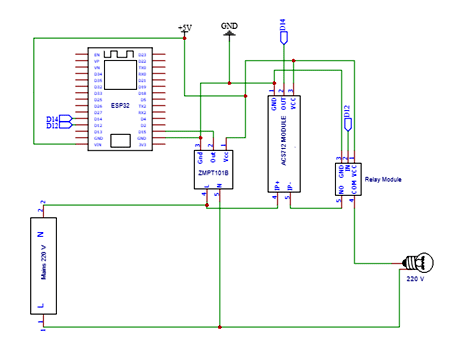
Consumer side meter Schematics same for the Distribution side except for Relay (only use on the consumer side). Current Sensor & ZMPT101B Voltage Sensor VCC is connected to Vin of ESP32 which is a 5V Supply. The GND pin of both the modules is connected to the GND of ESP32. The output analog pin of the ZMPT101B Voltage Sensor and Current Sensor is connected to ESP32. The voltage sensor is connected in parallel with mains and the Current Sensor in series, also the relay as a switch for the output.
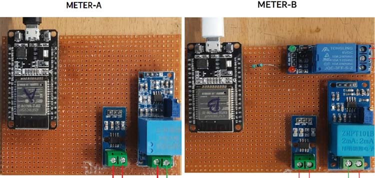
Also check our previous projects on Smart Electricity Meter for energy monitoring and power consumption calculation:
Meter A:

// Meter A (disturbution side meter )
#define BLYNK_PRINT Serial
//Dependiences
#include "EmonLib.h"
#include <WiFi.h>
#include <WiFiClient.h>
#include <BlynkSimpleEsp32.h>
EnergyMonitor emon;
// calibrate() method calibrates zero point of sensor,
#define vCalibration 160
#define currCalibration 1
//Global variable
char auth[] = "XUX_m5m1mOAlfD0jLelsjXmYPpitBDBf";//Token for Meter-A
char ssid[] = "MASTER";
char pass[] = "20042006";
//Bridge Widget Blynk Server
WidgetBridge bridge1(V10);
BLYNK_CONNECTED()
{
  bridge1.setAuthToken("MFP3HhJC8Yn8UEJV3N2pe_c9etEzFISx");  //(Meter B token )allow permission to write the values to Meter B
}
void setup()
{
  // Debug console
  Serial.begin(9600);
  WiFi.begin();
  Blynk.begin(auth, ssid, pass, IPAddress(192,168,2,184));// Put you Local machine IPAddress if using Local Machine as server
  // ZMPT101B sensor connected to GPIO 35
  emon.voltage(35, vCalibration, 1.7); // Voltage: input pin, calibration, phase_shift
  // Acs712 sensor connected to GPIO 34
  emon.current(34, currCalibration); // Current: input pin, calibration.
}
void loop()
{
  //-------------------------------------------------Data Setup---------------------------------------
  emon.calcVI(20, 2000);
 // Serial.println(String(" A ") + emon.Irms  + (" Voltage ") + emon.Vrms + (" Watts ") + emon.apparentPower );
  delay(100);
  Blynk.virtualWrite(V0, emon.Irms );// display amps temporary
  bridge1.virtualWrite(V1, emon.apparentPower);  // send Watt to Device B (Consumer meter for match )web interface
  delay(100);
  Blynk.run();
}

Meter B:

// Meter B (Consumer  side meter )
#define BLYNK_PRINT Serial
//Dependiences
#include "EmonLib.h"
#include <WiFi.h>
#include <WiFiClient.h>
#include <BlynkSimpleEsp32.h>
EnergyMonitor emon;
// calibrate() method calibrates zero point of sensor,
#define vCalibration 160
#define currCalibration 1
//Global variable
char auth[] = "MFP3HhJC8Yn8UEJV3N2pe_c9etEzFISx"; //Token for Meter-B
char ssid[] = "MASTER";
char pass[] = "20042006";
unsigned int Meter_A = 0; // create variable for Watts values received from Meter-A
int Relay = 13; //GPIO 13
int theft =  0; // Varible for Theft Aleart on Virtual Pin
int PD ; //Power difference
WidgetBridge bridge1(V10);
// Assign virtual pin 10 of this device for Bridge Widget
//to communicate with other Devices (Meter B) and the channel is named "bridge1"
void setup()
{
  // Debug console
  Serial.begin(9600);
   Blynk.begin(auth, ssid, pass, IPAddress(192,168,2,184));// Put you Local machine IPAddress if using Local Machine as server
  pinMode(Relay, OUTPUT);
  // ZMPT101B sensor connected to GPIO 35
  emon.voltage(35, vCalibration, 1.7); // Voltage: input pin, calibration, phase_shift
  // Acs712 sensor connected to GPIO 34
  emon.current(34, currCalibration); // Current: input pin, calibration.
}
void loop()
{
  //-------------------------------------------------Data Setup---------------------------------------
  emon.calcVI(20, 2000);
 // Serial.println(String("Current: ") + Amps + (" Volts: ") + emon.Vrms + (" Meter-B-Watts: ") + emon.apparentPower + ( "  Meter-A-Watts: ") + Meter_A + (" PD:") + PD) ;
 float Amps = emon.Irms;
  Blynk.virtualWrite(V0, emon.Vrms);
  Blynk.virtualWrite(V1, Amps);
  Blynk.virtualWrite(V2, emon.apparentPower);
  delay(100);
  Blynk.run();
  //---------------------------------------------------------Power Cutoff--------------------------------------------------
  PD = Meter_A - emon.apparentPower ;// Power difference in Meter A and Meter B
  if ((PD >= 10) && (PD >= -10)) {
    theft = 1 ;
    Blynk.virtualWrite(V3, theft);
    digitalWrite(Relay, LOW); // Reverse triger Relay (Low - on) &( High-off)
    delay(300);
  } else {
    digitalWrite(Relay, HIGH); //
    theft = 0 ;
    Blynk.virtualWrite(V3, theft);
    delay(300);
  }
}
// Power Feedback (Theft detection)
BLYNK_WRITE(V1) // V1 is th eVirtual Power Pin of Meter-A
{
  Meter_A = param.asInt();// Fetching Watts Data form Meter-A in integers
  delay(100);
}

